Location:Home Page > Archive Archive
Why is power supply ripple so big?
2023-05-08【Archive】
What is ripple?
Because a regulated DC power supply is usually formed by rectifying and stabilizing an AC power supply, it is inevitable that there are some AC components in regulated DC amount that are superimposed on regulated DC amount The AC component is called ripple. The composition of ripple is more complex, and its shape is generally a sinusoidal harmonic with a frequency higher than mains frequency, and other is a pulse wave with a narrow width. For different cases, requirements for pulsation are different.
The ripple expression method can be expressed in effective value or peak value, it can be expressed in absolute or relative amount. For example, if power supply operates in a stable voltage state, its output is 100V 5A, and measured effective ripple value is 10mV. These 10mV is absolute value of ripple, and relative value is ripple ratio = voltage ripple/output voltage= 10mV/100V=0.01%, which is equal to one ten-thousandth.
Why is power supply ripple so large?
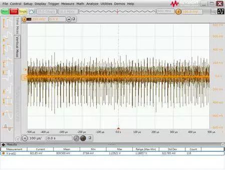
When user checked output ripple of 5V switching power supply with a 500MHz bandwidth oscilloscope, they found that peak-to-peak ripple and noise reaches over 900mV (as shown in figure below), while its peak-to-peak rated ripple of switching power supply is <20 mV. Although there is an LDO on back of user PCB to stabilize output of switching power supply, user considers measurement result to be too large and unreliable and hopes to find out problem.
01 Problem Analysis
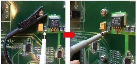
The problem of measuring excessive power ripple is usually related to sensor used and method of connecting external interface. First, I checked connection method of custom probe, and found that it uses a long ground wire with a crocodile clip, as shown in left picture below, and ground point is clamped on fixing screw of one board, and whole ground loop is relatively large. Since large ground loop will introduce more spatial electromagnetic radiation noise and ground loop noise caused by switching power supply, it is replaced with a short ground pin as shown in the right figure below.
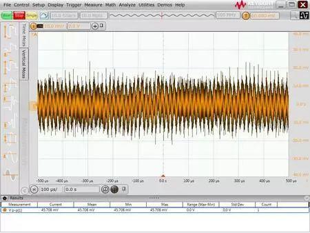
After actual testing, it was found that measured ripple noise amplitude improved significantly, as shown in figure below. However, noise ripple peak-to-peak is still over 40mV, which is still quite different from <20mV nominally claimed by switching power supply manufacturer.
Further inspection of probe model used by user reveals that user is using a standard 10:1 oscilloscope passive probe. as shown below.
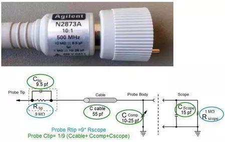
The 10:1 probe will attenuate measured signal by a factor of 10 before sending it to oscilloscope, and then oscilloscope will mathematically amplify measured signal by a factor of 10. The advantage of such a probe is that bandwidth of probe can be increased to hundreds of MHz by matching network in front, and also increase range of oscilloscope, but this is not particularly beneficial for measuring small signals. If amplitude of signal being measured is small, it may be buried in bottom noise of oscilloscope when attenuated by a factor of 10. Even with a mathematical gain of 10 times, signal-to-noise ratio itself will not be improved. Therefore, a low attenuation probe, such as a 1:1 probe, should be used as often as possible to measure power supply ripple noise. Therefore, I found another 1:1 passive probe. Although bandwidth of this 1:1 passive probe is small (usually tens of MHz), but attenuation coefficient is small, it is very suitable for testing small signals.
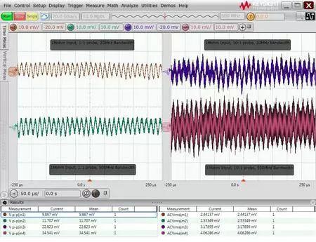
The figure below shows results of a comparative test of a 1:1 passive sensor and a 10:1 sensor under various bandwidth limitations. You can see that after using 1:1 probe and setting bandwidth limit to 20 MHz, measured ripple noise has a peak-to-peak value of less than 10 mV, which is much better than 10:1 probe test result. . Test results of 1:1 probe show a clear ripple waveform and meet user expectations for <20 mV power supply ripple noise. In addition, we can also see that bandwidth limit also has a certain effect on peak-to-peak noise.
02 Issue overview
This is a common problem when testing voltage ripple. We significantly improved our ripple noise test results by using a short ground, switching to a lower attenuation probe and limiting bandwidth. Generally speaking, influencing factors affecting power ripple test results are mainly as follows according to their importance:
1. Length of input connection line and ground loop: A long ground loop picks up more EMI and switching power supply ground noise, so use shortest ground connection possible.
2. Probe attenuation ratio: A probe with a high attenuation ratio will make a small signal amplitude weaker even if it is submerged by oscilloscope's noise floor, so you should try using a probe with a 1:1 attenuation ratio.
3. Bandwidth Limiting. Many oscilloscope EMI and noise floors are wideband, and setting appropriate bandwidth limiting can filter out additional noise. In many cases of power supply ripple and noise, a 20 MHz bandwidth limit is used, and some ICs require 80 MHz or 200 MHz measurement.
4. Measuring range: Typically, power ripple measurements are performed over a small range (eg 10 mV/div or 20 mV/div). The larger range, higher noise level of oscilloscope. However, some oscilloscopes have a limited offset range and may not be able to bring measured DC voltage signal back to center of screen for measurements on small gears, so in many cases oscilloscope's AC coupled function is used to isolate DC voltage before continuing. Ripple noise test.
5. Input impedance: Many oscilloscopes have 50Ω and 1MΩ input impedance options. Typically, noise floor of an oscilloscope with 50 ohm input impedance is lower. However, when connecting oscilloscope to most passive probes, impedance automatically switches to 1 MΩ. Only when connecting active probes or coaxial cables, you can set input impedance to 50 Ω.
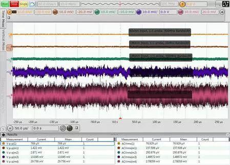
It's a good habit before actual test to check system's noise floor under current hardware and settings. The five waveforms in figure below are noise floor measurements using 500M S-Series oscilloscope with various probes and bandwidth settings. Waveforms from top to bottom: 50 ohm input impedance, 1:1 probe, 500 MHz bandwidth; 1 MΩ input impedance, 1:1 probe, 20 MHz bandwidth; 1 MΩ input impedance, 1:1 probe, 500 bandwidthMHz; input 1 MΩ. Impedance, 10:1 probe, 20 MHz bandwidth, 1 MΩ input impedance, 10:1 probe, 500 MHz bandwidth. The peak-to-peak noise floor ranges from less than 1 mV to almost 30 mV, showing the importance of probe settings, bandwidth, and input impedance in a test.
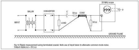
If you really don't have a suitable low attenuation probe on hand, you can also use a 50 ohm coax cable to make a probe as follows. In fact, one end of cable is connected to oscilloscope, and oscilloscope is set to 50 ohm input impedance, other end of cable is stripped, shield layer is welded to ground of circuit under test, and center conductor is connected to power signal under test through a DC coupling capacitor. The advantage of this method is low cost, low attenuation, and disadvantage is that consistency is not good, and the DC blocking capacitor and bandwidth are not easy to control. In addition, in recent years, oscilloscope manufacturers have also introduced probes specially designed for measuring power supply ripple, which combine low attenuation ratio (1.1:1), wide bandwidth (hardware frequency 2 GHz, bandwidth limit can be set software) and consider measurement needs and noise offset range (can reach ±24V), can simultaneously measure ripple and DC voltage, which is suitable for users who have high requirements for measuring power supply ripple.
Related
- Why is power supply ripple so big?
- What is power supply ripple, how to measure their magnitude and how to suppress?
- Four ways to reduce the output "ripple and noise" of a switching power supply
- Why is analog electronics so hard to learn?
- Engineer Daniel tells you: The "Y Capacitor" of a switching power supply is calculated in this way.
- Why is shielded wire so important? But remember about one-way grounding!
- Switching Power Supply PCB Design Skills
- Various losses inside switching power supply
- "Clear at a glance" inside power supply
- How does internal resistance affect a power supply?
Hot Posts
 How to distinguish induction from leakage, we will teach you three tricks! Ordinary people can also learn super practical
- What is drowning in gold? Why Shen Jin?
- This is a metaphor for EMI/EMS/EMC that can be understood at a glance.
- How many types of pads have you seen in PCB design?
- Summary of Common PCB Repair Techniques
- What is three anti-paint? How to use it correctly?
- Knowing these rules, you will not get confused looking at circuit diagram.
- How to make anti-interference PCB design?
- Can diodes do this?