Location:Home Page > Archive Archive
Engineer Daniel tells you: The "Y Capacitor" of a switching power supply is calculated in this way.
2023-04-15【Archive】
Principal diagram of a switching power supply
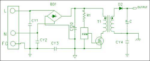
1. Main channel:
Connected directly to an external power supply.
2. Secondary circuit:
Part of circuit located inside device and isolated from primary side.
3. Y-capacitor:
A high voltage capacitor connected between primary circuit and ground or between primary and secondary circuits.
Switch-mode power supply grounding, leakage current, voltage withstand test (safety regulations)
1. Ground continuity test:
A. Definition:
Pass current from PG input terminal to a user-accessible ground terminal to ensure that its resistance value is less than specified value to perform ground protection function.
B. Standard:
1. Input current not more than 25 A, voltage (DC or AC) not more than 12 V, time not less than 3 seconds (TUV requirements).
2. Test result: resistance value should not exceed 100 mΩ.
2. Ground leakage current test:
A. Definition:
Using a "human body impedance simulation circuit" approved by safety regulations (UL, TUV, CSA...), measure current between accessible metal parts and earth when object under test (SPS) is turned on. amount of electric current passing through human body.
B. Standard:
1. The input voltage is 106% of upper limit of rated voltage.
2. Test results: class I ≤ 3.5 mA, class II ≤ 0.25 mA.
3. Voltage dielectric strength test:
A. Definition:
Also known as a high voltage dielectric test, i.e. a Hi-pot (high potential) test in which a high voltage is applied from primary winding to secondary winding (or from primary winding to ground) to determine if inner insulating layer has dangerous insulation voltage.
B. Standard:
1. The input voltage is as follows:
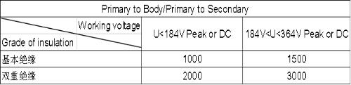
2. Test result: no insulation breakdown (breakdown).
Difference between AC and DC voltage withstand voltage test
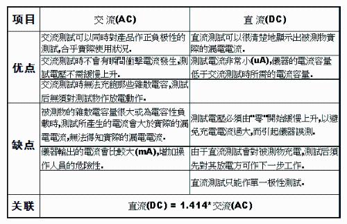
Method for calculating leakage current for voltage withstand test
1. DC leakage current setting:
The DC test current is very small (µA), usually a high DC voltage is applied between primary and secondary sides, and leakage current value: 0µA~100µA.
2. Theoretical calculation of leakage current for AC test:
Calculation formula: I =2π*f*V*Cy
Where:
f— test voltage frequency ( 50 Hz or 60 Hz )
V is test voltage (unit: Volt)
Cy is sum of Y capacitors connected to primary side and ground, or between primary and secondary sides.
So: Imin = 2π*f*V*Cymin
Imax = 2π*f*V*Cymax
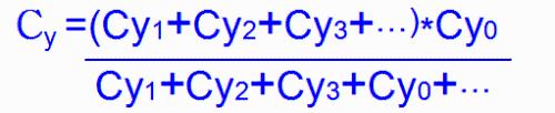
Capacity calculation Cy:: Cy =Cy1 Cy2 Cy3 …
If a Y-capacitor (Cy0 ) is connected between primary ground and secondary ground, then:
Y capacitance tolerance is typically: /-20% OR /-10%
3. When actually setting AC leakage test current, following factors must be considered:
1. Consider initial leakage current:
The initial leakage current is measured leakage current when DUT is not present.
2. Consider capacitance tolerance Y:
When electrical engineers choose Y capacitors of same capacity, they often have multiple models, but their tolerances vary (some /-10%, some /-20%), which creates problems with actual leakage current. So we have to set it according to /-20% tolerance. Otherwise, we must set it according to /-10% tolerance.
3. Consider dissipated capacitance that exists in a real circuit, so leakage current range is set to: (lower limit rounded up: upper limit rounded up)
Related
- Engineer Daniel tells you: The "Y Capacitor" of a switching power supply is calculated in this way.
- Detailed analysis of the "various protection schemes" of a switching power supply
- Finally, it becomes clear that process of obtaining switching losses of a MOSFET in a switching power supply
- Four ways to reduce the output "ripple and noise" of a switching power supply
- Analysis of damping RC circuit of a switching power supply "haberdashery"
- Analysis of various losses inside a switching power supply from 4 aspects
- The most complete knowledge in history of uninterruptible power supply UPS
- What is purpose of connecting a polar capacitor and a non-polar capacitor in parallel?
- Do not underestimate "form of high-frequency magnetic core" in switching power supply, what effect does it have on transformer?
- The best switching circuit design process for power supplies is a must for engineers!
Hot Posts
 How to distinguish induction from leakage, we will teach you three tricks! Ordinary people can also learn super practical
- What is drowning in gold? Why Shen Jin?
- This is a metaphor for EMI/EMS/EMC that can be understood at a glance.
- How many types of pads have you seen in PCB design?
- Summary of Common PCB Repair Techniques
- What is three anti-paint? How to use it correctly?
- Knowing these rules, you will not get confused looking at circuit diagram.
- How to make anti-interference PCB design?
- Can diodes do this?