Location:Home Page > Archive Archive
Knowing these rules, you will not get confused looking at circuit diagram.
2023-03-30【Archive】
It's unavoidable to look at pictures when we do DIY electronics, but for many beginners, it always feels messy at beginning. The editor uses electronic circuit diagram as main example for summing up.
Scheme trend
refers to direction of each circuit part on circuit diagram from start input terminal to end output terminal. The most common circuit diagram direction is left to right, which means that each signal processing block diagram is laid out in a left to right direction. Some schemes also use top-down orientation.
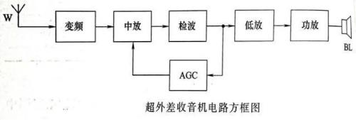
For example, in figure above, wireless signal comes from left W antenna, and from left to right passes frequency conversion, middle amplifier, detection, bass amplifier and power amplifier, and finally outputs sound. from BL speaker. But AGC (automatic gain control circuit) in figure is used as a feedback circuit, and its direction is from right to left. In other words, feedback circuit returns part or all of output signal back to input terminal, and its direction is opposite to that of the main circuit.
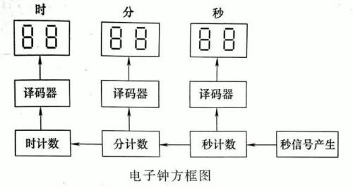
For some complex circuit diagrams, for some reason, some circuits are also reversed when above rules are generally followed, but arrow symbols are usually used to indicate direction of circuit. As shown in figure above: in order to symbolize people's habits of arranging time "hour", "minute" and "second", direction of electrical circuit is taken from left to right and from bottom to top, which is relatively rare. .
Orientation and drawing style of graphic symbols
The national standard circuit diagram graphics provide only basic graphics, but we can change orientation and position of these graphics to suit specific real-world usage needs.
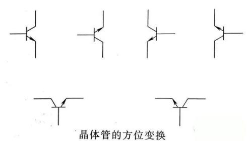
Component symbology orientation can be placed horizontally or vertically, up or down, rotated or mirrored to suit drawing needs. The NPN transistor symbol shown above.
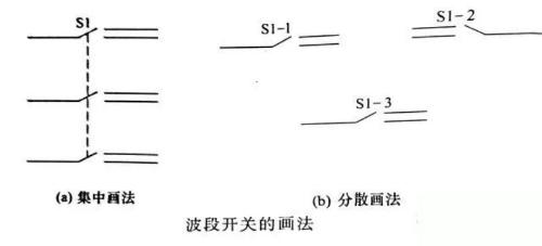
Some components include multiple components, and centralized drawing method and scattered drawing method can be used in circuit diagram according to need. As shown in figure above: Ribbon switches can be drawn together as shown in figure a, and connected with dotted lines to indicate connection; they can also be drawn respectively next to circuits they control, as shown in figure b, and use text symbols "C1-1" and "C1-2" to mean "C1-3".
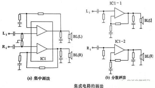
Some components contain many independent blocks, especially integrated circuits, such as bi-amplification integrated circuit in above figure, figure a is centralized drawing method, and figure b is diffuse drawing method. Generally speaking, simpler circuits use a centralized drawing method, while more complex circuits use a scattered drawing method.
Status of running components
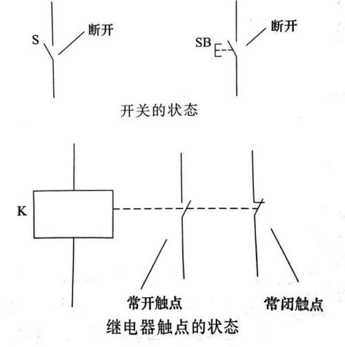
Working devices with moving parts, such as switches and relays, show their operating state when not in use on a circuit diagram. As shown above, switch is in off state, normally open contact of relay is in open state, and normally closed contact is in closed state.
Integrated circuit drawing method
The internal circuitry of an integrated circuit is typically very complex, with several blocks and many components, but an integrated circuit is usually considered only as a component in a circuit diagram. Therefore, on almost all circuit diagrams, internal circuit of an integrated circuit is not drawn, but is depicted as a holding or triangular frame.
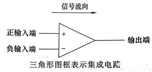
Integrated op-amps, voltage comparators, etc. are traditionally shown as triangular boxes. As shown in figure above, there are positive and negative input terminals on left side, and output terminal is at top of triangle on right side, and direction of top of triangular frame corresponds to direction of flow. signal.
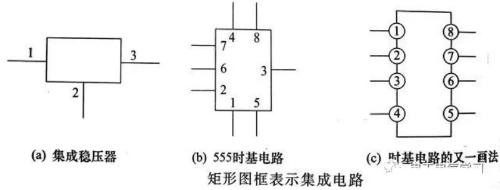
As shown in figure above, built-in voltage regulator, time base circuit, etc. are usually shown as a rectangular box, and each terminal is marked with a pin number. The pin numbers can be marked outside box, inside box, or on a rectangular box, and pin numbers can be in order or out of order. Most other types of integrated circuits are represented by rectangular boxes.
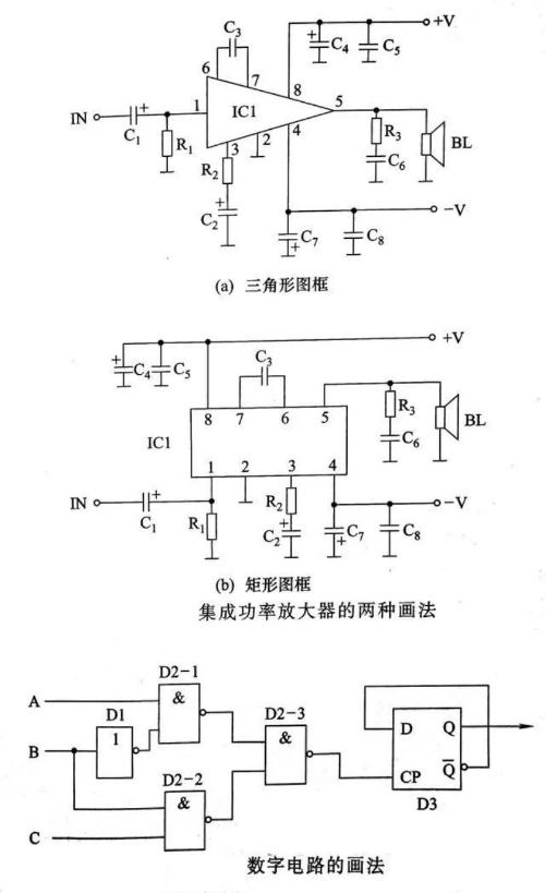
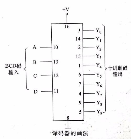
As shown in figure above, voltage integrated amplifiers, integrated power amplifiers, etc. are represented by triangular or rectangular boxes, but amplifiers are represented by triangular boxes, and signal flow is more intuitive. Digital integrated circuits generally use a diffuse drawing method, which is directly represented by logical graphic symbols, and gate circuits, flip-flops, etc. all use this drawing method. Other digital integrated circuits are still mostly represented by rectangular boxes, and text symbols of contact logic functions are marked on each pin, as shown in decoder in figure below.
Representation of connecting wires
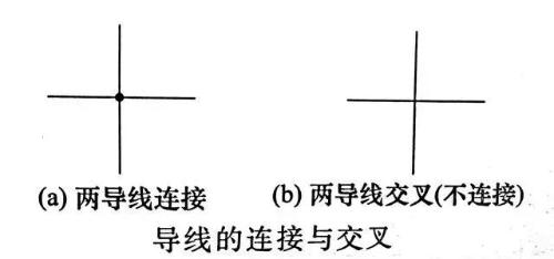
Connecting wires between components are represented in circuit diagram by solid lines. In figure a, there is a dot at intersection of two wires, which means that two wires are connected together; in figure b, there is no point at intersection of two wires, which means that two wires intersect but are not connected.
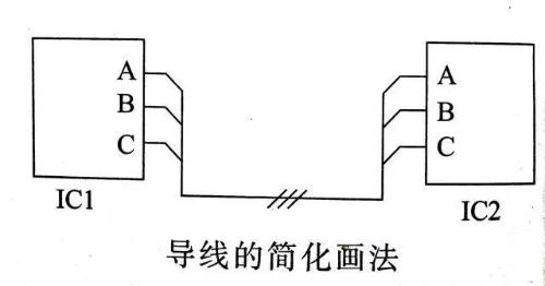
You can use a simplified drawing to connect wires. For example, in above figure, there are 3 small slashes drawn on connection line between IC1 and IC2, which means there are 3 wires connecting A and A, B and A IC1 and IC2 respectively B, C and C are connected together, but these 3 wires are not connected.
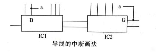
When two ends of connecting wire are far apart and there are more graphics areas in middle, interrupt and mark drawing method can be used. As shown in figure above, connection wire between IC1's B terminal and IC2's G terminal uses interrupt drawing method, and two ends of interrupt are marked with same "a" mark. in diagram, this is understood as two "between terminals a" there is a connecting wire.
Representation of non-electrical connections
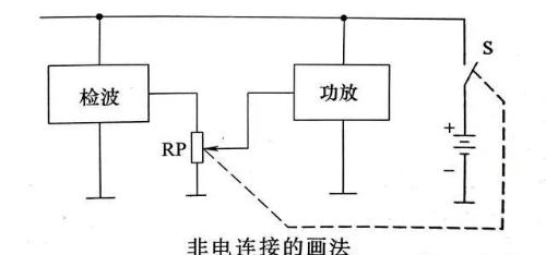
There is a mechanical connection between certain components, which is shown in circuit diagram with dotted lines. As shown in figure below, dotted line connects RP potentiometer to S switch, indicating that power switch is controlled by rotary shaft of volume potentiometer, and they are associated potentiometer with switch.
Picture of power line and ground line
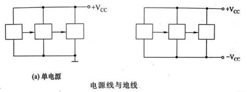
Typically, place power line or positive power wire in a dual power supply above components, and place ground wire or negative power wire in a dual power supply below components.
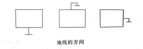
Generally, ground symbol is drawn downwards, but sometimes it can also be drawn up, left, or right, as dictated by layout of drawing.
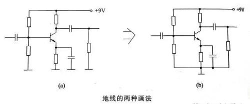
More complex circuits often do not connect all ground wires together, but instead use individual ground symbols one after other.
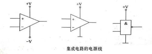
Normally, power leads of op amps and digital integrated circuits are not drawn on circuit diagram because it does not affect circuit analysis function, but power leads should not be forgotten when analyzing power circuits and real production.
Related
- Knowing these rules, you will not get confused looking at circuit diagram.
- Does circuit diagram actually contain that much truth?
- 3 MOSFET device selection rules that will teach you how to become a device selection wizard
- step-down capacitor pay attention to these six points, do not need to worry about circuit analysis
- How many of these free and easy to use circuit design programs have you used?
- In digital form? Imitation? Don't get confused by engineering design
- Is printed circuit board covered with copper very “up to mark”? One article to help you get practical guidelines and norms
- PCB puzzle, these few special rules!
- What is difference between surge device, lightning arrester, leakage protection, circuit breaker and circuit breaker? Come and get knowledge
- 40 Practical Analog Circuit Tips That 90% of People Will Ignore
Hot Posts
 How to distinguish induction from leakage, we will teach you three tricks! Ordinary people can also learn super practical
- What is drowning in gold? Why Shen Jin?
- This is a metaphor for EMI/EMS/EMC that can be understood at a glance.
- How many types of pads have you seen in PCB design?
- Summary of Common PCB Repair Techniques
- What is three anti-paint? How to use it correctly?
- Knowing these rules, you will not get confused looking at circuit diagram.
- How to make anti-interference PCB design?
- Can diodes do this?