Location:Home Page > Archive Archive
Three circuit diagrams to teach you how to understand how a buck RC works
2023-03-18【Archive】
The principle of operation of a capacitive buck converter is not complicated. The principle of operation of an RC buck converter is to use capacitive reactance generated by a capacitor at a certain frequency of an AC signal to limit maximum operating current. In this case, resistive element is connected in series with capacitor, and voltage obtained at both ends of resistive element and power generated by it are completely dependent on characteristics of resistive element.
So capacitive bucking actually uses capacitive reactance to limit current, and capacitor actually plays role of limiting current and dynamically sharing voltage between capacitor and load.
For example, at a mains frequency of 50 Hz, capacitive reactance created by a 1 uF capacitor is about 3180 ohms. When 220V AC is applied to both ends of capacitor, maximum current flowing through capacitor is about 70mA. Although current flowing through capacitor is 70 mA, no power is generated on capacitor because if capacitor is an ideal capacitor, current flowing through capacitor is imaginary part current and work it does is reactive power .
According to this function, if we connect a resistive element in series with a 1uF capacitor, voltage across resistive element and power consumed by it will depend entirely on characteristics of resistive element. For example, we connect a 110V / 8W light bulb in series with a 1uF capacitor, when it is connected to AC 220V / 50Hz, light bulb will light up and emit normal brightness without burning out. Since current required for a 110V/8W incandescent lamp is 8W/110V=72mA, it is consistent with current limiting characteristics of a 1uF capacitor.
Similarly, we can also connect a 5W/65V light bulb and a 1uF capacitor in series to a 220V/50Hz AC power supply, and light bulb will also burn without burning out. Because working current of 5W/65V lamp is also about 70mA. So capacitive bucking actually uses capacitive reactance to limit current. The capacitor actually plays role of current limiting and dynamic voltage distribution between capacitor and load.
Figure 1 is a typical application of capacitance step-down resistance, C1 is step-down capacitor, R1 is C1 discharge resistor when power off, D1 is half-wave rectifier diode, D2 is discharging. for C1 in negative half-cycle of network circuit, otherwise capacitor C1 will not work when it is fully charged, Z1 is a zener diode, and C2 is a filter capacitor. The output is a stable voltage value of zener diode Z1.
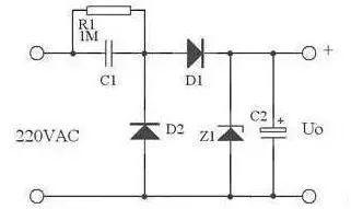
Picture 1
In practical applications, you can use Figure 2 instead of Figure 1. Here, Z1's forward and reverse characteristics are used, and its inverse characteristic (i.e., its voltage stabilization characteristic) is used to stabilize voltage. discharge circuit for C1 in negative half-cycle of network.
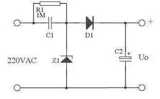
Picture 2
For high current applications, full-wave rectification can be used, as shown in fig. 3.
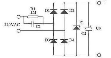
Picture 3
When low voltage is full wave rectification, maximum output current is:
Capacity Xc=1/(2πfC)
Current Ic = U/Xc=2πfCU
Pay attention to following points when using capacitors to reduce voltage:
1) Select appropriate capacitor according to load current and AC operating frequency, not according to load voltage and power;
2) Current limiting capacitors must be non-polar, electrolytic capacitors are not allowed. The voltage of capacitor should be higher than 400V. The ideal capacitor is an oil capacitor with an iron case.
3) Capacitive voltage reducer cannot be used in high power environment because it is unsafe;
4) Step-down capacitors are not suitable for dynamic load conditions;
5) 5. Capacitive voltage reducer is not suitable for capacitive and inductive loads;
6) When DC operation is required, half-wave rectification should be used as much as possible. Bridge rectifiers are not recommended. But to meet conditions of constant load.
Related
- Three circuit diagrams to teach you how to understand how a buck RC works
- How to design a triode amplifier circuit
- How to distinguish induction from leakage, we will teach you three tricks! Ordinary people can also learn super practical
- 3 MOSFET device selection rules that will teach you how to become a device selection wizard
- How many of these free and easy to use circuit design programs have you used?
- What skills should I pay attention to when designing a triode amplifier circuit? (Easy to understand)
- How to choose a suitable power chip, do you know this?
- How to independently check malfunction of parallel resistance circuit? Chart details
- What is three anti-paint? How to use it correctly?
- MOS tube drive circuit, how to make MOS tube turn on and off quickly?
Hot Posts
 How to distinguish induction from leakage, we will teach you three tricks! Ordinary people can also learn super practical
- What is drowning in gold? Why Shen Jin?
- This is a metaphor for EMI/EMS/EMC that can be understood at a glance.
- How many types of pads have you seen in PCB design?
- Summary of Common PCB Repair Techniques
- What is three anti-paint? How to use it correctly?
- Knowing these rules, you will not get confused looking at circuit diagram.
- How to make anti-interference PCB design?
- Can diodes do this?