Location:Home Page > Archive Archive
How to design a triode amplifier circuit
2023-03-20【Archive】
01
Analysis Design Requirements
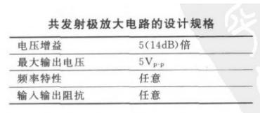
The voltage gain can be used to calculate voltage gain, maximum output voltage can be used to set the power supply voltage.
The emitter current can be calculated from output power, frequency characteristics should be paid attention to when choosing a transistor.
02
Determine supply voltage
The first figure shows that maximum output voltage amplitude is 5V, and triode output voltage amplitude is determined by Vc pole voltage, and Vc terminal voltage should be set to about 1/2. supply voltage.
Here we set power supply voltage to 15V. To make positive and negative signal have a symmetrical change space, when there is no input signal, that is, input signal is 0, assuming that Uce is half of power supply voltage, we take it beyond horizontal line used as a reference point.
When input signal increases, Ib increases and current Ic increases, then voltage U2=Ic×R2 of resistor R2 increases accordingly, and Uce=VCC-U2 decreases. Theoretically, U2 can reach a maximum equal to VCC, and Uce can reach a minimum of 0 V. That is, as input signal increases, maximum change in Uce is from 1/2 VCC to 0 V.
Similarly, when input signal decreases, Ib decreases, and current Ic decreases, then voltage U2=Ic×R2 of resistor R2 decreases accordingly, and Uce=VCC-U2 increases. When input signal decreases, maximum change in Uce is from 1/2 VCC to VCC. Thus, when positive and negative changes occur within a certain range of input signal, if Uce is based on 1/2VCC, there will be a symmetrical range of positive and negative changes.
03
Choose a crystal diode
Things to pay attention to when using a triode:
1) Is withstand voltage sufficient
2) Is load current large enough?
3) Is speed fast enough (sometimes slow)
4) Is there enough current to control pole B?
5) Sometimes power problems can occur
6) Sometimes it is necessary to consider problem of leakage current (can it be "completely" cut off)
7) In general, gain is not considered large (my application has not yet required a high level of this parameter)
04
Determining emitter current Ie
By relationship between frequency response of radiator and frequency response of radiator. The emitter current of a low-signal common emitter ranges from 0.1 to several milliamps.
05
Determine Rc and Re values
Usually Vce is set to half VCC, Vce=Ic*(Rc+Re), Rc and Re refer to increase.
06
Determine value of underlying bias chain R1 and R2
We know value of Ic from Ic=β*Ib (β is usually assumed to be 100) and then we estimate current value flowing through R1, which is usually about 10 times greater than Ib. Calculate R1 and R2.
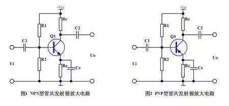
R1 and R2 are DC bias resistors of triode V1. What is DC bias? In other words, you need food to work. In order for a triode to work, certain operating conditions must first be provided, and electronic components must require power, otherwise it is not called a circuit. In working requirements of circuit, first condition must be stable, so power supply must be a DC power supply, so it is called DC bias. Why power is supplied through a resistor A resistor is like a faucet in a water supply that is used to regulate current. Therefore, three operating states of stop, saturation, and gain triode are determined by DC bias, in Fig.Unke 1 it is determined by resistors R1 and R2.
07
Identify coupling capacitors C1 and C2
C1 and input impedance, C2 and terminating resistor connected to output end respectively form a high pass filter. It is necessary to obtain values of C1 and C2 by calculating center frequency.
C1 and C2 are coupling capacitors. Communication is transmission of signals. Capacitors can transmit signal signals from front stage to back stage because voltage at both ends of capacitor cannot change dramatically. Since voltage cannot change suddenly, voltage at output terminal will change along with input AC signal at input terminal, thereby coupling signal from input terminal to output terminal. But it should be noted that voltage across the capacitor cannot change suddenly, but it is not impossible to change either.
Related
- How to design a triode amplifier circuit
- What skills should I pay attention to when designing a triode amplifier circuit? (Easy to understand)
- Hardware Circuit Design Specification: A Very Good Reference to Hardware Design
- Three circuit diagrams to teach you how to understand how a buck RC works
- How many of these free and easy to use circuit design programs have you used?
- Sample Analysis! Tell us about the skills of triode amplifier circuitry.
- The best switching circuit design process for power supplies is a must for engineers!
- How to make anti-interference PCB design?
- How to independently check malfunction of parallel resistance circuit? Chart details
- Industrial Computer Circuit Design
Hot Posts
 How to distinguish induction from leakage, we will teach you three tricks! Ordinary people can also learn super practical
- What is drowning in gold? Why Shen Jin?
- This is a metaphor for EMI/EMS/EMC that can be understood at a glance.
- How many types of pads have you seen in PCB design?
- Summary of Common PCB Repair Techniques
- What is three anti-paint? How to use it correctly?
- Knowing these rules, you will not get confused looking at circuit diagram.
- How to make anti-interference PCB design?
- Can diodes do this?