Location:Home Page > Archive Archive
What skills should I pay attention to when designing a triode amplifier circuit? (Easy to understand)
2023-05-04【Archive】
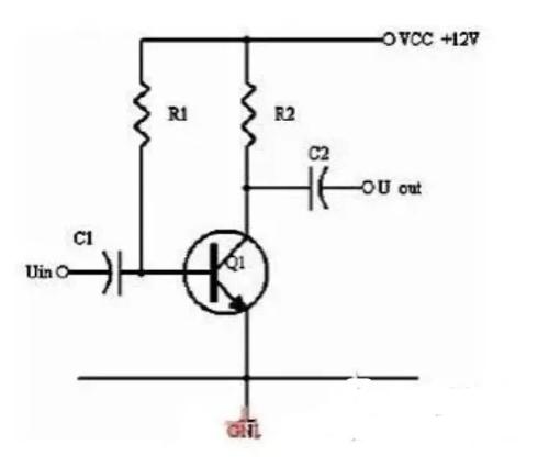
The main component of amplifier circuit is triode, so it is necessary to have some understanding of triode. There are many types of amplifying circuits made up of triodes, and we will use most commonly used ones to explain them (as shown in Figure 1). The basic common-emitter amplifier circuit is shown in Figure 1. In general, what do we need to know about amplifier circuit?
(1) Analyze function of each component in circuit;
(2) amplification principle to release large chains;
(3) Be able to analyze and calculate static operating point of a circuit;
(4) Understand purpose and method of setting a static operating point;
Of four points above, last one is more important.
Picture 1
In Figure 1, capacitors C1 and C2 are decoupling capacitors. Communication is transmission of signals. Capacitors can carry signal signals from front stage to back stage because voltage at either end of capacitor cannot change dramatically. After AC signal is input to input terminal, since voltage at both ends cannot change abruptly, voltage at output terminal will change along with input AC signal at input terminal, thereby linking signal from input terminal to output terminal. But it should be noted that voltage across capacitor cannot change suddenly, but it is not impossible to change either.
R1 and R2 are DC bias resistors of triode V1. What is DC bias? Simply put, work requires food. In order for a triode to work, certain operating conditions must first be provided, and electronic components must require power, otherwise it is not called a circuit.
In working requirements of circuit, first condition must be stable, so power supply must be a DC power supply, which is why it is called DC bias. Why is power supplied through a resistor? A resistor is like a faucet in a water supply that is used to regulate current. Therefore, triode's three operating states "load stop, saturation, boost" are determined by DC bias, in Figure 1 it is determined by resistors R1 and R2.
First of all, we need to know how to distinguish between three operating states of a triode. In simple terms, one can judge what operating state is based on size of Uce. If Uce is close to VCC voltage, triode will operate in load.state, load-stop state means that triode is not working at all, and current Ic is small (near zero), since no current flows through R2, voltage close to 0V, so Uce is close to power supply voltage VCC.
If Uce is close to 0V, triode is in saturation. What is saturation state? That is, current Ic has reached its maximum value, even if Ib increases, it cannot increase any more.
The above two states are commonly referred to as switching states. Except for these two states, third state is an amplification state. Typically, Uce is close to half power supply voltage. If measured value of Uce is biased towards VCC, triode is usually in a load state, and if measured value of Uce is biased towards 0 V, triode is usually in a saturation state.
Understand purpose and method of setting a static operating point
The purpose of amplification circuit is to amplify input signal and its output (typically voltage amplification, current amplification, and power amplification, which are not discussed here). Let's first talk about signal we want to amplify, using an AC sine wave as an example. In percentIn analysis essay, you can only take into account whether change in signal size is positive or negative, and nothing else. It was mentioned above that in amplifier circuit shown in Figure 1, static operating point is set to Uce close to half supply voltage, why?
This is to ensure that positive and negative signal have a symmetrical change space. When there is no input signal, that is, input signal is 0, assuming Uce is half of power supply voltage, we consider it as a horizontal line as a reference point. When input signal increases, Ib increases and current Ic increases, then voltage U2=Ic×R2 of resistor R2 increases accordingly, and Uce=VCC-U2 decreases. Theoretically, U2 can reach a maximum equal to VCC, and Uce can reach a minimum of 0 V. That is, as input signal increases, maximum change in Uce is from 1/2 VCC to 0 V.
Similarly, when input signal decreases, Ib decreases, and current Ic decreases, then voltage U2=Ic×R2 of resistor R2 decreases accordingly, and Uce=VCC-U2 increases. When input signal decreases, maximum change in Uce is from 1/2 VCC to VCC. Thus, when positive and negative changes occur within a certain input signal range, if Uce is based on 1/2VCC, there will be a symmetrical range of positive and negative changes. Therefore, static operating point in Figure 1 is usually set so that Uce is close to half power supply voltage.
Our goal is to design Uce to be close to half power supply voltage, but how can we design Uce to be close to half power supply voltage? This is a remedy.
There are a few things to be aware of here. First, we often call Ic and Ib. These are collector current and base current of triode. They have ratio Ic=β×Ib. At time, teacher obviously didn't tell us how big Ic and Ib should be? This question is harder to answer because there are many things involved, but generally speaking for low power lamps, Ic is usually set from zero to a few milliamps, and for medium power lamps, from a few milliamps to tens. milliamps., high-power lamps range from tens of milliamps to several amperes.
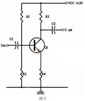
In figure 1, if Ic is 2mA, resistance value of R2 can be calculated as R=U/I, VCC is 12V, then 1/2VCC is 6V, and R2 is 6V/2mA . 3 kOhm Ic is set to 2mA, then Ib can be deduced from Ib=Ic/β, key is value of β, and total theoretical value of β is 100, then Ib=2mA/100=20#A, then R1=(VCC -0, 7V)/Ib=11.3V/20#A=56.5kΩ, but in fact β value of low power lamp is much more than 100, between 150 and 400 or higher, so if above calculation is done, circuit can be in withsaturation state, so sometimes we do not understand that calculation is correct, but it cannot be used in practice, because there is still a little practical guide to point out difference between theory and practice. This type of circuit is heavily influenced by value of β. When everyone calculates same way, results will not necessarily be same. That is, stability of this scheme is poor, and there are few practical applications. But if it is replaced by voltage divider bias circuit in Fig. 2, analytical calculation of circuit will be closer to actual measurement of circuit.
Picture 2
In voltage divider bias circuit in Figure 2, we also assume that Ic is 2mA and Uce is designed so that 1/2VCC is 6V. So how should R1, R2, R3, R4 be set? The calculation formula is as follows: Since Uce is designed so that 1/2VCC is 6V, then Ic×(R3+R4)=6V, Ic≈Ie. We can calculate that R3+R4=3KΩ, so how much do R3 and R4 cost? Typically, R4 is 100 ohms and R3 is 2.9 k ohms. In fact, R3 is usually 2.7 k ohms, because there is no 2.9 k ohms in E24 series resistors, and there is not much difference between 2.7 k ohm value and 2.9 kOhm. Because voltage across R2 is Ube+UR4.
0.7V + 100Ω × 2mA = 0.9V, we set Ic to 2mA, and total theoretical value of β is 100, then Ib = 2mA/100 = 20#A, current needs to be estimated, which is current flowing through R1 Current, total value is about 10 times Ib, take IR1200#A.
Then R1=11.1V/200#A≈56kΩ R2=0.9V (/200-20) #A=5kΩ Given that actual value of β can be much greater than 100, actual value of R2 is 4.7 kOhm Thus, values of R1, R2, R3 and R4 are 56kΩ, 4.7kΩ, 2.7kΩ and 100Ω respectively, and Uce is 6.4V.
In above analysis and calculation, assumptions have been made many times, which is necessary in practical applications. Many times we need a reference value for calculation, but often there is none. I'm not familiar with device, and second is to forget one thing, we are those who use scheme, some data can be set by ourselves so that we can avoid workarounds.
Related
- What skills should I pay attention to when designing a triode amplifier circuit? (Easy to understand)
- How to design a triode amplifier circuit
- "Easy to understand" Miller effect when switching MOS lamps
- step-down capacitor pay attention to these six points, do not need to worry about circuit analysis
- Three circuit diagrams to teach you how to understand how a buck RC works
- When designing a power supply, how to consider choice of topology?
- Sample Analysis! Tell us about the skills of triode amplifier circuitry.
- Easy to understand! Explain PID
- Pay attention to PCB vias
- Did you pay attention to details of using relay?
Hot Posts
 How to distinguish induction from leakage, we will teach you three tricks! Ordinary people can also learn super practical
- What is drowning in gold? Why Shen Jin?
- This is a metaphor for EMI/EMS/EMC that can be understood at a glance.
- How many types of pads have you seen in PCB design?
- Summary of Common PCB Repair Techniques
- What is three anti-paint? How to use it correctly?
- Knowing these rules, you will not get confused looking at circuit diagram.
- How to make anti-interference PCB design?
- Can diodes do this?