Location:Home Page > Archive Archive
There are several types of MOS lamp drive circuits, you will understand after reading.
2023-08-18【Archive】
MOS lamps are widely used in switching power supplies due to their low internal conduction resistance and high switching speed. In order to use a MOS lamp effectively, design of its drive circuit is very important. Below are a few commonly used drive circuits.
01 Power IC direct drive
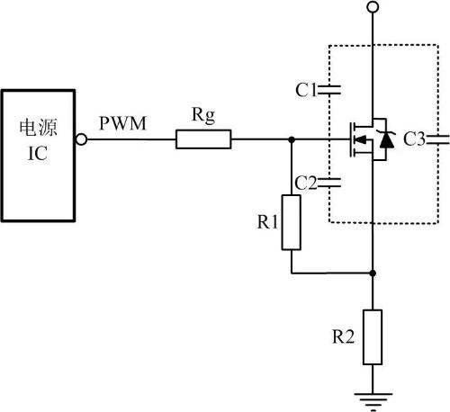
Direct control of a power IC is simplest control method, and several parameters and effect of these parameters should be taken into account.
① Check maximum peak drive current in power IC manual, because power of different ICs often varies.
② Understand parasitic capacitance of MOS tube, as shown in values of C1 and C2, smaller parasitic capacitance, better. If values of C1 and C2 are relatively large, energy required to conduct MOS tube will be relatively large. If power supply IC does not have a relatively large drive peak current, then tube conduction speed will be relatively slow and desired effect will not be achieved.
02 Two-stroke drive
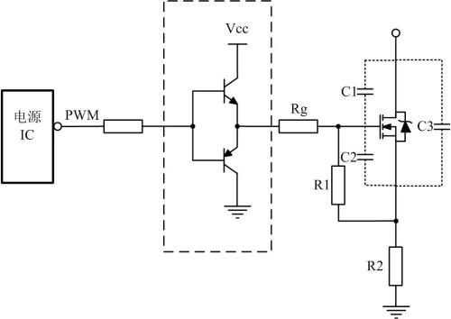
When control capabilities of power IC are not sufficient, push-pull control can be used.
The advantage of this control circuit is to improve current supply capability and quickly complete charging process of charging input gate capacitor. This topology increases turn-on time but reduces turn-off time. The switch tube can be turned on quickly and avoid high-frequency rising edge oscillations.
03 Speed up drive shutdown
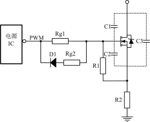
MOS lamps typically turn on slowly and turn off quickly. At turn-off moment, control circuit can provide a path with as low an impedance as possible to quickly discharge capacitor voltage between gate and source of MOSFET to ensure that switching tube can be turned off quickly. .
To quickly discharge capacitive voltage between gate and source, a resistor and a diode are often connected in parallel with leading resistor, as shown in figure above, where D1 is usually used as a fast recovery diode. . This reduces downtime and reduces shutdown losses. Rg2 is designed to prevent too much current when turning off and burning power IC.
As shown in picture above, this is layout I used before. Serially produced at least tens of thousands of units. Recommended to use.
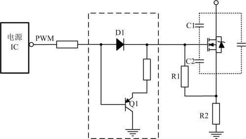
A triode is more commonly used to discharge capacitive voltage between gate and source. If emitter of Q1 has no resistance when PNP transistor is on, capacitance between gate and source is short-circuited, so that charge is discharged in shortest time, and turn-off transient loss is minimized. .
Another advantage is that when capacitance between gate and source is discharged, no current flows through power supply IC, which improves reliability.
04 Insulated Disk
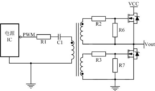
To match drive of high quality MOS lamps, a transformer drive is often used. The purpose of R1 is to suppress parasitic inductance on PCB and C1 to generate LC oscillations. The purpose of C1 is to separate DC and pass AC, preventing core saturation.
Related
- There are several types of MOS lamp drive circuits, you will understand after reading.
- You will understand difference between input impedance and output impedance after reading this article!
- Where to start studying inductance? I will understand after reading
- 44 types of practical schemes, you will master, you will know everything!
- You will understand difference between input impedance and output impedance by reading this article.
- Do you understand MOS driver in motor controller?
- MOS tube drive circuit, how to make MOS tube turn on and off quickly?
- Do you understand all this knowledge of inductance?
- "Easy to understand" Miller effect when switching MOS lamps
- In circuit design, what are differences between six types of grounds?
Hot Posts
 How to distinguish induction from leakage, we will teach you three tricks! Ordinary people can also learn super practical
- What is drowning in gold? Why Shen Jin?
- This is a metaphor for EMI/EMS/EMC that can be understood at a glance.
- How many types of pads have you seen in PCB design?
- Summary of Common PCB Repair Techniques
- What is three anti-paint? How to use it correctly?
- Knowing these rules, you will not get confused looking at circuit diagram.
- How to make anti-interference PCB design?
- Can diodes do this?