Location:Home Page > Archive Archive
Do you understand MOS driver in motor controller?
2023-03-18【Archive】
Introduction
The I/O voltage of a general purpose MCU or DSP is typically 5V to 3V, and I/O output current is below 20mA, which is not enough to directly drive a power MOSFET. Therefore, when using a general purpose MCU or DSP to develop a motor driver, it usually needs to be equipped with an external MOSFET driver, which we call "pre-driver". When developing motor drive controllers for automotive fans, water pumps, oil pumps, etc., the use of automotive MCU + automotive pre-driver + automotive N-channel power MOSFET can adapt to different power, different communication methods and different control methods.
Power MOS driver in controller
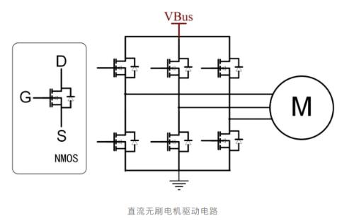
As shown above, power stage drive circuit of a three-phase brushless DC motor (including brushless DC motor and PMSM) uses six N-channel MOSFETs to form a three-phase full bridge, which is divided into three high-level sides connected to positive power supply pole (VBus). The MOS and three low-side MOSs are connected to negative pole of power supply. The controller completes commutation by controlling on/off of six MOSFETs so that motor rotates as expected. The motor may stall during operation and cause overcurrent, so MOSFET drive circuit must have a protection function to prevent controller or motor from burning out.
For a single CMOS, when turned on, an instantaneous high current must be provided to charge parasitic capacitance in MOS. After gate-to-source voltage (VGS) reaches a certain threshold, MOS can be fully turned on. Once MOS is turned on, a suitable gate-to-source voltage (VGS) must be maintained before it can remain on.
For a low-side MOSFET, source (S) is connected to negative pole of power supply, gate-source voltage is easily observed, and control is relatively simple.
For a high level MOSFET, its source (S) is connected to motor phase line and its voltage is unknown. If it needs to be enabled, gate voltage must be provided through bootstrap circuitry. , and drive is more complicated.
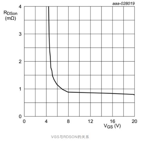
In general, on-state MOS resistance is shown in figure above, it decreases as VGS increases, but after VGS exceeds 10V, decrease curve becomes smooth. To achieve Minimum On-State Resistance (RDSON), VGS is typically 10-15V.
Related
- Do you understand MOS driver in motor controller?
- Do you understand all this knowledge of inductance?
- Why do diodes conduct electricity in one direction? understand in seconds
- "Easy to understand" Miller effect when switching MOS lamps
- Do you know layout requirements of some special devices in PCB design?
- Understand in seconds! How gyroscopes work
- Understand Current Detection Circuit in One Article
- 11 Essential Knowledge Points About Mos Tube If You Don't Read Them, You'll Be Missing A Lot
- "Jingzhen" stroked you: "Do you know how I work?"
- You will understand difference between input impedance and output impedance after reading this article!
Hot Posts
 How to distinguish induction from leakage, we will teach you three tricks! Ordinary people can also learn super practical
- What is drowning in gold? Why Shen Jin?
- This is a metaphor for EMI/EMS/EMC that can be understood at a glance.
- How many types of pads have you seen in PCB design?
- Summary of Common PCB Repair Techniques
- What is three anti-paint? How to use it correctly?
- Knowing these rules, you will not get confused looking at circuit diagram.
- How to make anti-interference PCB design?
- Can diodes do this?