Location:Home Page > Archive Archive
"Dry cargo sharing", switching power supply, "creepage distance" and "electrical clearance".
2023-12-03【Archive】
Summary
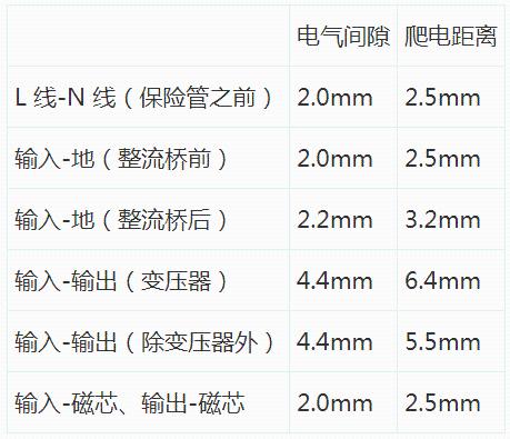
Cleaning distance: The shortest path between two conductive parts, or between a conductive part and equipment enclosure interface, measured along an insulating surface. Electrical clearance: The shortest spatial distance measured between two conductive parts or between a conductive part and protective interface of equipment. That is, in case of ensuring stable and safe electrical performance, shortest distance that can be insulated by air. Generally speaking, value required for creepage distance is greater than value required for electrical clearance, and requirements for both must be met when wiring (that is, distance between surface and space must be considered), grooves (slot width) must be greater than 1 mm) can only increase surface distance, that is, creepage distance, and cannot increase electrical clearance, so when electrical clearance is not enough, slot cannot solve this problem. whether position and length of slot meet requirements of creepage distance. Electrical isolation distance of components and printed circuit boards: (electrical isolation distance refers to a comprehensive consideration of electrical clearance and creepage distance) for switching power supplies of class I equipment ( ● Class I equipment: equipment that uses basic insulation and protective earth to protect against electric current ). (a switched-mode power supply with a grounded case belongs to this type of equipment); ● class II equipment: equipment that uses other means than relying solely on basic insulation (eg double insulation or reinforced insulation) to protect against electric shock; ● class III equipment: no danger of electric shock), insulation distance between components and printed circuit boards is as follows: (the following values do not include fields). A. For AC/DC power supply (Do not use power factor correction circuit and input rated voltage range of 100~240VAC as an example)
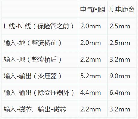
b. For AC/DC power supply (take PFC circuit and input rated voltage range 100~240VAC as an example)
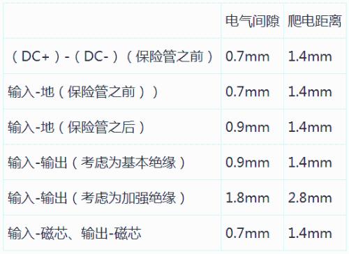
c. For DC power supply (take input rated voltage range of 36-76V as an example)
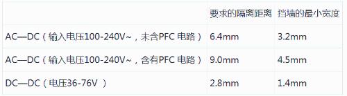
1. Electrical isolation inside transformer
The electrical insulation distance inside transformer refers to sum of widths of barrier walls on both sides of transformer. If width of transformer barrier wall is 3mm, electrical insulation distance of transformer is 6mm (the width of barrier walls on both sides is same). If transformer does not have a retaining wall, then insulation distance of transformer is equal to thickness of adhesive tape used. In addition, for AC-DC power supply, three layers of adhesive tape should be used to insulate primary and secondary windings of transformer, while for DC-DC power supply, only two layers of adhesive tape can be used for insulation. The following values do not include margin:
Note. If transformer pins are not covered with insulating sleeves, insulation distance on pins can only be thickness of tape plus wall thickness, so transformer pins must be covered with insulating sleeves and pipe must pass through retaining wall.
Space distance (creepage distance): shortest straight-line distance measured between two conductive components, or between a conductive component and an interface between objects across an air separation; clearance along an insulating surface: between two conductive components, measured along an insulating surface Sometimes or shortest distance between a conductive component and interface of an object. and shell and accessible part If distance between them is insufficient, conductive components can be wrapped with insulating material. Wrapping conductive components with insulating material solves not only creepage distance but also clearance. This method is commonly used for transformer winding when distance between transformer and surrounding components on power board is insufficient. In addition, voltage difference between two conductors can be appropriately reduced without compromising function of product.
Second, determining electrical gap
Distance can be determined from measured operating voltage and insulation level
See Table 3 and Table 4 for primary side circuit clearance requirements. Secondary side circuit clearance requirements are generally as follows: Primary side AC portion: L—N ≥ 2.5mm to fuse, L.N PE (earth) ≥ 2.5 mm, after fuse is not required, but keep a certain distance as far as possible to avoid a short circuit in power supply. Primary side AC to DC part ≥ 2.0 mm Primary side DC ground to ground ≥ 2.5 mm (primary side floats between ground) Primary side part to Secondary side part ≥ 4.0 mm, components connected between primary and secondary sides The clearance of secondary side part is ≥0.5mm, and grounding of secondary side is ≥1.0mm to ground. Distance, so that it is confirmed that worst case spatial distance is still in line with regulations.
3. Creepage path determination
Usually:
(1), primary side AC part: L—N ≥ 2.5mm before fuse, L.N ground ≥ 2.5mm, after fuse no requirement, but try to keep a certain distance to avoid short circuit. damage to power supply circuit. (2), AC primary side to DC part ≥ 2.0mm (3), DC primary sideground current to ground ≥ 4.0 mm, e.g. primary side ground to ground (4), primary side to secondary side ≥ 6.4 mm, e.g. optocoupler, Components such as Y-capacitors pitched ≤6.4 mm , must have slots. (5), ≥ 0.5 mm between parts of secondary winding (6), grounding of secondary winding to earth ≥ 2.0 mm or more (7), transformer between two stages ≥ 8.0 mm or more
4. Insulation penetration distance
The following rules must be observed depending on operating voltage and insulation:
——For operating voltage not exceeding 50V (71V AC peak or DC value), there is no requirement for thickness;——The minimum thickness of supplementary insulation should be 0.4mm;——When reinforced insulation is not is subjected to any mechanical action that deforms or destroys insulating material, minimum thickness of reinforced insulation shall be 0.4 mm. The above requirements do not apply to thin layers of insulating material, regardless of thickness, if insulation provided is used inside protective enclosure of equipment and will not be knocked down or worn by operator during maintenance and is either: - additional insulation, at least two layers of material are used, each of which can withstand electric strength test for additional insulation; - for supplementary insulation consisting of three layers of material, can withstand any combination of two layers of material Pass dielectric strength test for supplementary insulation insulation; - for reinforced insulation, at least two layers of material are used, each of which can withstand dielectric strength test of reinforced insulation; – for reinforced insulation consisting of three layers of insulating material, a combination of any two layers of materials may pass dielectric strength test of reinforced insulation.
5. What to look for when connecting
Flat components such as capacitors must be mounted on a flat surface without spreading out. For example, distance between two conductors can be reduced by applying a force of 10 N.
When laying PVC film in some shell equipment, pay attention to safety distance (pay attention to processing technology) and fix parts with glue. Be careful not to get foreign objects such as glue threads on circuit board. . When processing parts, it should not cause damage to insulation.
6.Requirements for fire-resistant materials
Heat shrink tubing V-1 or VTM-2 or higher; casing PVC V-1 or VTM-2 or higher
Teflon housing V-1 or VTM-2 or higher; plastic material such as silicone sheet, electrical tape V-1 or VTM-2 or higher PCB 94V-1 or higher
Seven, about isolation level
(1), functional insulation: insulation required for normalequipment operation
(2), basic insulation: insulation providing basic protection against electric shock (3), supplementary insulation: independent insulation applied in addition to basic insulation to protect against electric shock in event of failure of basic insulation (4) Double insulation: insulation consisting of basic insulation plus supplementary insulation (5) Reinforced insulation: single insulation construction, under conditions specified in this standard, level of protection against electric shock it provides is equivalent to double insulation
8. Creepage path determination
First you need to define type of insulation:
Basic insulation: working insulation between primary circuit and protective earth ①: inside primary circuit, internal working insulation of secondary circuit ②: inside input part (before input relay), secondary circuit and protective earthReinforced insulation: primary circuit and secondary circuit, input part and primary circuit, charging board output and internal circuit, and then check circuit to determine voltage difference between lines Table 1: Creepage distance
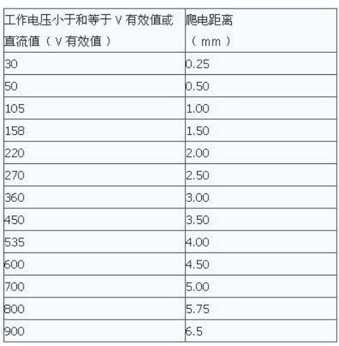
Finally, find appropriate creepage distance from table below
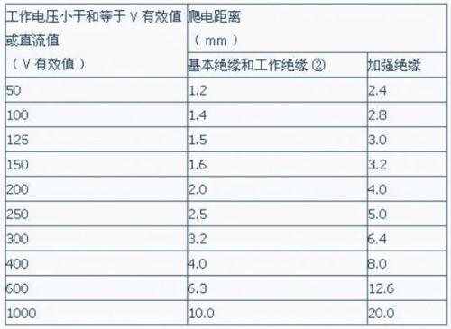
Table 2 creepage distances (applies to basic insulation, functional insulation②, reinforced insulation)
9. Determining electrical gap
First you need to define type of insulation:
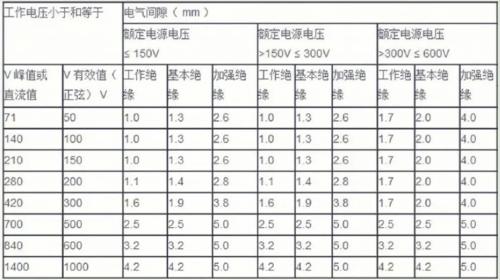
Basic insulation: working insulation between primary circuit and protective earth ①: inside primary circuit, internal working insulation of secondary circuit ②: inside input part (up to input relay), secondary circuit and protective earth Reinforced insulation: primary circuit and secondary circuit, input part is connected to primary circuit, output of charging board and internal circuit are checked again to determine voltage difference between lines, finally find out corresponding electrical clearances from table below (between, primary circuit, input circuit, input circuit and other circuits)
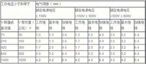
Table 4 Electrical clearances (applicable to the secondary circuit)
10. Basic steps for adjusting creepage distance and clearance
1. Steps to determine electrical clearance
Determine peak value and effective value of operating voltage; determine supply voltage of equipment and category of power supply object; determine magnitude of transient overvoltage applied to equipment in accordance with overvoltage category; determine pollution level of equipment (common equipment has a pollution level of 2); determination of type of insulation for through bridge (functional insulation, basic insulation, additional insulation, reinforced insulation).
2. Determine step of creepage distance Determine rms value or DC value of operating voltage, determine material group (according to comparative tracking index, it is divided into: material group I, material group II, material group IIIa, IIIb Note: If material group is unknown, it is assumed that material belongs to group IIIb); determine degree of pollution; determine type of insulation (functional insulation, basic insulation, additional insulation, reinforced insulation).
3.Determine required electrical clearance value.According to measured operating voltage and insulation level, see table (4943: 2H and 2J and 2K, table 60065-2001: Table 8, Table 9 and Table 10) to obtain required electrical gap distance can be determined; as an alternative electrical clearance method, 4943 is superseded by Appendix G and 60065-2001 is superseded by Appendix J. GB 8898-2001: The main factor to consider when selecting electrical clearance is operating voltage. For its definition, see fig. 9. (For conductive parts connected to a power supply network with an effective voltage value in range of 220-250V, these values \u200b\u200bare equal to values \u200b\u200bcorresponding to a peak voltage of 354V: basic insulation 3.0mm, reinforced insulation 6.0mm)
4. Determine required creepage distance. According to operating voltage, insulation level and material group, check table (GB 4943 is table 2L and 65-2001 is table 11) to determine creepage distance value. When table is between two voltage ranges, internal difference method must be used to calculate creepage distance. The design value according to GB 8898-2001 is equal to electrical clearance. If following three conditions are met, electrical clearance and creepage distance can be reduced by 2 mm for reinforced insulation and 1 mm for basic insulation: 1) These creepage distances and clearances will be reduced by external forces Small, but not located between accessible conductive parts of enclosure and hazardous conductive parts 2) are held in place by a rigid structure 3) their insulating properties are not seriously affected by external influences from dust generated inside equipment. *Note: However, you cannot zoom outdistance, creepage distance and electrical clearance between parts of different polarity directly connected to mains supply. Even if basic and supplementary insulation do not meet creepage distance and clearance requirements, as long as insulation is short-circuited, equipment still meets standard requirements, which is acceptable (4.3.1 of 8898). * In GB 4943, only clearance and creepage distance of functional insulation can be reduced, but they must withstand high voltage or short circuit tests specified in standard 5.3.4.
5. Determine creepage distance and electrical clearance. Please note that moving parts must be in most unfavorable position, value of creepage distance cannot be less than value of electrical clearance, it has passed mechanical load test;
Related
- "Dry cargo sharing", switching power supply, "creepage distance" and "electrical clearance".
- Sharing 9 circuit designs switching power supply, circuit diagram, circuit board, application notes
- Four ways to reduce the output "ripple and noise" of a switching power supply
- The composition of switching power supply circuit and a detailed explanation of general circuits
- Switching Power Supply PCB Design Skills
- Various losses inside switching power supply
- The principle of operation of a switching power supply "Exchange of haberdashery" and a circuit diagram
- Notes on whole switching power supply design process!
- Analysis of damping RC circuit of a switching power supply "haberdashery"
- (In-depth long text) Detailed interpretation of switching power supply circuit
Hot Posts
 How to distinguish induction from leakage, we will teach you three tricks! Ordinary people can also learn super practical
- What is drowning in gold? Why Shen Jin?
- This is a metaphor for EMI/EMS/EMC that can be understood at a glance.
- How many types of pads have you seen in PCB design?
- Summary of Common PCB Repair Techniques
- What is three anti-paint? How to use it correctly?
- Knowing these rules, you will not get confused looking at circuit diagram.
- How to make anti-interference PCB design?
- Can diodes do this?