Location:Home Page > Archive Archive
Analysis of damping RC circuit of a switching power supply "haberdashery"
2023-04-12【Archive】
01 Problem Background
In our widely used AC/DC switching power supply, instantaneous reverse pulse generated on secondary coil due to leakage inductance of primary coil is very serious. As shown in Figure 1, this is an AC/DC circuit built on MPS MP020-5 chip. Here, waveforms are measured at both ends of Schottky diode in secondary. We know that greatest function of Schottky diode is to prevent transient reverse pulse of primary coil of transformer from affecting subsequent circuit through secondary coil. If shock pulse causes a short circuit, then switching power supply chip will break instantly. Here I'm using a transformer with a primary to secondary ratio of 1:3 and our total reverse instantaneous impulse is around 700-1000V or even more. Impulse voltage is about 224V. We can see Schottky diodes connected in parallel with RC circuit in many AC-DC power supply circuits, but we don't know how to choose values of these two components, because in a real design we may not follow circuit. It is required to choose same transformer, for example, recommended MPS020-5 transformer turns ratio is 1:11, but considering actual volume of transformer, we change it to 1:3, then changing turns ratio will cause secondary reverse instantaneous impulse is different, so there is a strict requirement for reverse withstand voltage of Schottky diode. So, how to make RC really play a role and reduce cost of Schottky diodes, or what role does this RC play. In this article, this question is discussed with you from an experimental point of view.
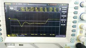
Picture 1
Appendix: MP020-5 switching power supply circuit
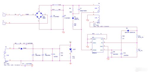
Picture 2
02 Analysis Problem
In terms of systems management theory, we model this secondary circuit as shown in Figures 3 and 4.
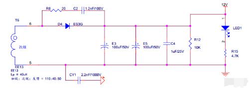
Picture 3
Picture 4
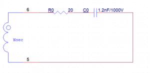
Here, since capacitor tends to short-circuit when switching power supply is turned on, subsequent stages R12 and R15 are short-circuited, and equivalent of capacitor C0 is capacitors E3, E5, connected in parallel and then in series with C2. The calculation of series-connected capacitors is equivalent to calculation of resistors in parallel, that is, smaller capacitor in a series connection, smaller equivalent capacitance, so we calculate directly from smallest capacitance C2, that is, equivalent capacitance C0 is 1.2 nF, and inductance of transformer. Secondary winding, resistance R8 (equivalent resistance R0) is value we need to measure.
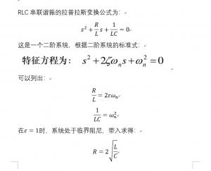
According to Kirchhoff's voltage law, write RLC series resonance differential equation, and then perform Laplace substitution. We can see that this model is a resonant circuit of RLC series. In control system, this is For a typical second - order system, see fig. 5 and fig. 6 for a specific formula derivation.
Picture 5

Picture 6
This is a typical second-order continuous system. If we look again at waveform diagram in Fig. 7, we find that this is a transient image. The transient response is characteristic generated at moment switching power supply is turned on.
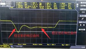
Picture 7
In a second-order system, transient response mainly occurs in three states: underdamping, critical damping, and overdamping.
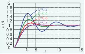
Plot of underdamped response. Rice. 8
Underdamping Due to underdamping, system will exceed steady state value at time of response, and then slowly fall to steady state value due to oscillation. The curve in above figure shows underdamped condition. In other words, our voltage should not reach 224V, but due to inertia of system, after reaching a stable value, it exceeds stable value, reaches maximum value, and then slowly drops to keep range of stable value Inside.
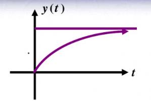
Plot of critical damping response. Rice. 9
Because damping is sufficient at critical damping, system will slowly rise to a steady value at time of response and no inertia will be generated. We need such a waveform. The derivation of Laplace transform formula for resonance of RLC series is shown in Figure 10.
Picture 10
The L value measured by bridge is 260 mH, L value is value of transformer secondary inductance, C is 1.2 nF, and resistance R is 1658 ohms.
03 Testing
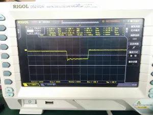
According to theoretical value obtained, it can be obtained that critical damping can be achieved at around 1658 ohms. In practice, there is no 1658 ohm resistor at hand, maximum is only 357 ohms, and pads are only enough to put two resistors in series, so I put two resistors in series. A 357 ohm resistance is connected in series to get a 714 ohm resistance, and then circuit is tested. The following figure shows measured waveform in Figure 11.
It can be seen that at moment of operation, system quickly reached a steady state, and underdamped shock impulse that had appeared before was eliminated, and reverse voltage was clamped at level of -156V. resistance value can not If it is too large, after reaching a certain value, system will cross critical damping, and value of this resistance is a range. Another thing is that capacitance here should be as small as possible, at level of nF, if it is too large, microcircuit will explode. In general, after determining RC value, we can effectively suppress larger voltage effect on Schottky diode caused by inertia of secondary reverse pulse. The benefit of this allows us to understand reason for existence of RC and, of course, can save material costs. Formerly SS320 with 200V reverse withstand voltage was used, which often exploded, later ES3G with 400V reverse withstand voltage was used. Although it can be used, material is relatively expensive. With this simple method, you can achieve greater cost savings.
Picture 11
Related
- Analysis of damping RC circuit of a switching power supply "haberdashery"
- Detailed analysis of the "various protection schemes" of a switching power supply
- Analysis of various losses inside a switching power supply from 4 aspects
- Finally, it becomes clear that process of obtaining switching losses of a MOSFET in a switching power supply
- Analysis of power circuit of a classic single-chip microcomputer
- Four ways to reduce the output "ripple and noise" of a switching power supply
- Engineer Daniel tells you: The "Y Capacitor" of a switching power supply is calculated in this way.
- 6500 words about switching power supply design, haberdashery, collect first, then study!
- Analysis and comparison of 6 most commonly used DC power supply circuits
- When designing a power supply, how to consider choice of topology?
Hot Posts
 How to distinguish induction from leakage, we will teach you three tricks! Ordinary people can also learn super practical
- What is drowning in gold? Why Shen Jin?
- This is a metaphor for EMI/EMS/EMC that can be understood at a glance.
- How many types of pads have you seen in PCB design?
- Summary of Common PCB Repair Techniques
- What is three anti-paint? How to use it correctly?
- Knowing these rules, you will not get confused looking at circuit diagram.
- How to make anti-interference PCB design?
- Can diodes do this?