Location:Home Page > Archive Archive
How to effectively use an oscilloscope? Even senior engineers overlook these details...
2023-03-18【Archive】
What is an oscilloscope trigger mode?
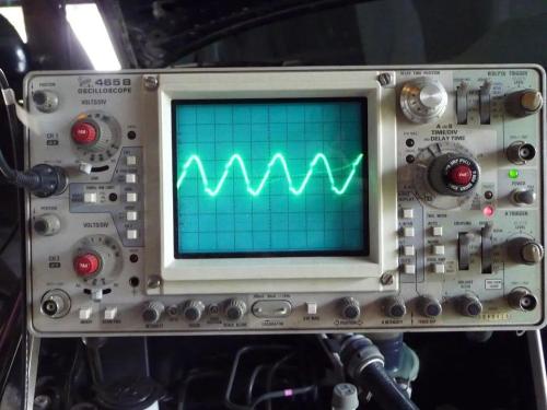
The oscilloscope's "trigger" must synchronize oscilloscope's scan to observed waveform in order to display a stable waveform. Different "start modes" are required to meet different surveillance needs. There are three basic trigger modes for oscilloscope:
The first one is "Auto mode (AUTO)":
In this mode, when trigger fails, oscilloscope's scanning system will automatically scan according to set scan rate;
When a trigger occurs, scanning system will try to scan according to frequency of signal, so in this mode, whether trigger condition is met or not, oscilloscope will scan, and you can see changed line sweep of screen, this is characteristic of this model .
Second - "Normal mode/Normal mode (NORM)":
This mode is different from automatic mode. In this mode, oscilloscope will only scan when trigger condition is met. If there is no trigger, oscilloscope will not scan.
So if there is no trigger in this mode, then analog oscilloscope will not see baseline and nothing on screen, and digital oscilloscope will not see waveform update. I often think that signal is not working. I connected it or something.
Third option - "SINGLE mode (SINGLE)":
This mode is a bit like "Normal Mode", i.e. only if trigger condition is met, a scan will be generated, otherwise no scan will be performed.
The difference is that once this scan is generated and completed, oscilloscope's scan system will enter a rest state, even if there is a signal later that satisfies trigger condition, it will not scan again, i.e. trigger once Scan only once, that is, once, and scanning system must be manually restarted in order to generate next trigger.
Obviously, with conventional analog oscilloscopes in this mode, you often find yourself unable to see anything because waveform flickers past and oscilloscope cannot hold it. In most cases, this mode is useless. The above three trigger modes are supported by most oscilloscopes.
How to choose and use it in practice?
In actual use, choice of different trigger modes should be evaluated according to characteristics of observed signal and observed content. There are no fixed rules, but it is often an interactive process, i.e. choosing different trigger modes to understand signal characteristics and choose an effective trigger mode according to signal characteristics and content you want to watch.
The most important thing in this process is to understand mechanism of operation of various launch modes, to understand characteristicssticks observed signal and clarify what should be observed.
Generally speaking, when characteristics of signal are poorly understood, you should choose automatic mode, because at that time oscilloscope will scan no matter what signal is, and you can at least see something on screen, even if it is only sweep lines are also good, but for good reason.
Once scanline is available, you can "find" signal by adjusting parameters such as vertical gain, vertical position, and temporal base speed, and then stabilize signal by selecting trigger source, trigger edge, and trigger level . .
For an analog oscilloscope, if signal is periodic, its frequency is within range suitable for observation with corresponding oscilloscope, and it is not too difficult, you can usually get a general idea of the signal. through such steps, and then it can be used as needed for further observations.
It may seem to many friends that there is no difference in monitoring effect in normal mode compared to auto mode. It is often case that waveform on screen does not change when trigger mode is switched between auto and normal. The situation often occurs only when observed signal is a relatively simple periodic signal.
The role of normal mode is to observe details of waveform, especially for more complex signals such as video sync signals. Why do you say that?
This is because in order to see details, we have to increase scan rate of time base in order to widen waveform. And when we do this, frequency of observed signal becomes lower compared to sweep frequency of oscilloscope, that is, oscilloscope can sweep many times between two triggers.
In this case, if we select auto mode at this time, oscilloscope will actually do all of these sweeps. The displayed waveforms are displayed together, resulting in an overlap of displayed waveforms, so waveforms we want to see cannot be displayed clearly.
And if we choose normal mode, those scanning oscilloscopes between triggers will not actually run, only those scans generated by triggers will be run, so only waveforms we want to see associated with triggers will be displayed, so waveform will be clearer, which is a function of normal trigger mode.
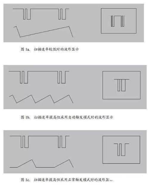
An illustration of this situation is shown in Figure 1. In Figure 1, observed waveform is shown at top left, scanned waveform at bottom, and waveform display at right.
Scan speed in fig. 1a low, which makes it difficult to observe signal details;
In fig. 1b scan speed increased and used automaticallytic start mode. At this time, displayed waveform is fuzzy and has an overlapping phenomenon;
Scan rate in fig. 1c is same as in Fig. 1b, but normal timing mode is used to scan only when a trigger is present, which allows a clear waveform to be displayed.
We have briefly described main oscilloscope trigger modes and their practical use, hoping to help beginners in mastering oscilloscope.
In addition to content discussed in this article, setting other oscilloscope settings is also very important. On one hand, users must have a clear understanding of meaning of various parameter settings.
On other hand, it is necessary to understand characteristics of observed signal and clarify purpose of observation so that oscilloscope can be used effectively to achieve purpose of measurement and testing.
How to use an oscilloscope correctly and efficiently?
Power supply engineers, when there is a problem with a product, need to capture waveform, fix timing, and check exact value to help engineer analyze and fix problem. Speak with facts and watch waveforms. It is very important how to make test data accurate and reliable.
Accurate numbers can help us, but distorted waveforms and values can only mislead us, make us run in opposite direction, make us go astray and do a lot of useless work.
After thinking carefully, although I'm not that strong in oscilloscope research, I read many articles about oscilloscopes, encountered many problems in practice, and solved many problems. I still have some experience. share it with you, I hope it will be useful for everyone. If letter is bad, please forgive me.
I often see that oscilloscopes used by many small companies are too cheap, with low bandwidth and low sampling rates. .
Seeing how they work with oscilloscope, they don't prepare for test, but just take it and use it. In fact, doing so is wrong. It can often be case that this incorrect operation leads to a distortion of test results and influences analysis. Even some very high-ranking engineers may miss some details.
Many engineers don't understand oscilloscopes, and ways to use them more effectively still need to be improved. Next, I'll fix problems many engineers often do and share some of knowledge I have.
1. Many engineers immediately take a probe and test without checking if probe needs to be compensated or if oscilloscope needs to be calibrated. Only some large companies or trained engineers do preparatory work before use. Before using oscilloscope, a self-calibration and probe compensation adjustment is required to match probe to input channel.
When using instrument for first time and displaying data from multiple input channels at same time, it may be necessary to calibrate vertical and horizontal data to synchronize timebase, amplitude, and position.For example, calibration is required for significant temperature changes (> 5°).
1. Disconnect any sensors or cables from channel input connectors. Make sure appliance is running and warming up for a while. From R File menu choose Selfalignment.
2. On Manage tab, click Start Leveling.
3. In R. Alignment Status field, results of individual calibration steps for each input channel are displayed on Results tab.
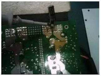
The steps for setting probe compensation are as follows: 1. Connect oscilloscope probe to channel and press PRESET button on front panel (in settings area on left panel). Connect probe signal terminal and reference ground to reference output on oscilloscope panel and press Autoset. When using a probe tip with a hook, securely connect tip of signal pin to probe to ensure proper connection. As shown in Figure 1:
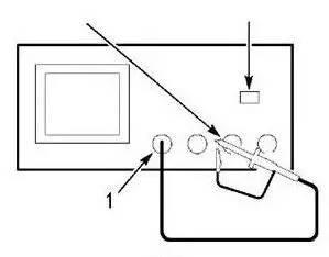
Group image 1 Sensor compensation setting
2. Check displayed waveform. The situation that may arise is shown in Figure 2.
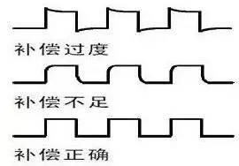 Rice. 2. Overcompensation, Undercompensation and Correct Compensation
Sensor adjustment required for both overshoot and undershoot. To better check exact value.
3. If waveform is not correct, adjust sensor. As shown in fig. 3 below until waveform is correct compensation waveform above.
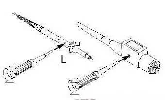
Fig. 3. Compensation probe method
The above two points seem simple, but engineers often overlook them. To make measurement more accurate, be sure to pay attention to inspection. These two calibration functions should be available on any oscilloscope.
2 Ripple test voltage
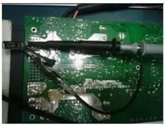
Many power engineers do not pay so much attention to measuring pulsations and take them for granted. Different ways to use an oscilloscope lead to large differences in test results. As shown in figures 4 and 5 below, for same product and same test point, due to differences in test methods, test results vary greatly. Ripple is an important parameter for a power supply, but it is not worth spending a lot of effort and money on fixing it if it fails test due to its own problems in operation.
Sometimes your customers may receive incorrect test data due to insufficient use and insufficient attention to instrument. But with my own products, there is no problem, and there is no point in doing this so that customers think they are being deceived, so testing method is very important. Paying attention to these details can save you a lot of time and improve your ability.
The value checked by oscilloscope itself has errors (I won't explain it here yet). Nowadays, many companies require value of test waveform as a basis for judgment. In fact, oscilloscope is only for checking process of voltage change over time, mainly for capturing signals during debugging. The specific accuracy of dc rms measurement is not as good as that of a digital multimeter. An oscilloscope DC accuracy calibration is also based on using a multimeter as a reference. But more and more companies and engineers consider value of an oscilloscope to be real value, so we can only do our best to keep test error to a minimum.
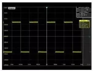
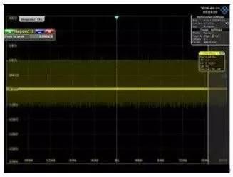
Below is chart and analysis of test ripple:
 Group photo four
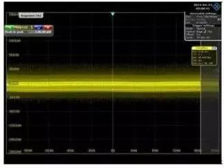
 Group photo 5
The resulting ripple value in fig. 4 is 3.9921 V, which is much larger than 0.126 V in fig. 5, but test value in fig. 4 is not true. Problem Analysis: There are no real problems with product. It's just a problem with testing method. Now let's point out problem:
The first mistake is to use a long ground wire.
The second mistake is placing both sensor circuit and ground wire near power transformer and switching elements.
The third error is excessive inductance between oscilloscope probe and output capacitor.
Due to this inattention, many high-frequency signals, magnetic field of transformer, and electric field of switch were captured, so that waveform captured by oscilloscope was doped with high-frequency noise and displayed.
The fourth error is that range is too large.
Accurate testing of Ripple requires:
Use bandwidth limiting for ripple measurements to prevent picking up high frequency noise that isn't actually there. The bandwidth of oscilloscope can be set to 20M. Remove probe "cap" and ground clamp to prevent antenna from interfering with long ground wires. Wrap ground wire between probe and ground.
Rohde & Schwarz specifically provided appropriate short ground wires. You may consider connecting 0.1uF and 10uF capacitors in parallel between signal and ground for decoupling. The length of capacitor's PIN also affects value of test.
Related
- How to effectively use an oscilloscope? Even senior engineers overlook these details...
- (Detailed long text) 7 ways to use diodes that engineers need to master
- How many of these free and easy to use circuit design programs have you used?
- Why are circuit boards mostly green? See what these 20+ engineers have to say
- What is three anti-paint? How to use it correctly?
- How to independently check malfunction of parallel resistance circuit? Chart details
- How to solve the problem with electrostatic discharge? Use several real cases to conduct a joint analysis
- The size, withstand voltage and direction of capacitor, how to choose these parameters?
- "English abbreviations" that equipment engineers need to know
- A Few Design Tips PCB Engineers Need to Know
Hot Posts
 How to distinguish induction from leakage, we will teach you three tricks! Ordinary people can also learn super practical
- What is drowning in gold? Why Shen Jin?
- This is a metaphor for EMI/EMS/EMC that can be understood at a glance.
- How many types of pads have you seen in PCB design?
- Summary of Common PCB Repair Techniques
- What is three anti-paint? How to use it correctly?
- Knowing these rules, you will not get confused looking at circuit diagram.
- How to make anti-interference PCB design?
- Can diodes do this?