Location:Home Page > Archive Archive
How to solve the problem with electrostatic discharge? Use several real cases to conduct a joint analysis
2023-05-01【Archive】
Smartwatch turned on and off repeatedly after triggering ESD near side button
Judging by timing of repeated reboots, it looks like a long press on power button. Check Power_On signal and find that it is constantly turning off. The schematic diagram of Power_On signal is as follows:
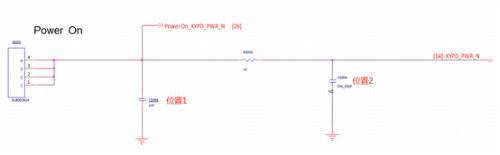 In order to reduce cost, FA tube is not attached to position 1, but instead a capacitor is used, withstand voltage of which is 25V. The failed machine had a capacitor short circuit, and it can be concluded that electrostatic discharge entered case and directly damaged capacitor in position 1.
If withstand voltage of capacitor in position 1 is increased to 50V, number of anti-static guns that can withstand will increase, but they will still eventually be damaged. This project is not waterproof, and sealing is poor, so there is a problem.
[Solution]
Replace capacitor in position 1 with a TVS tube or do not glue anything in position 1 and put a 1nF capacitor in position 2. Rely on a 1K resistor + 1nF capacitor to absorb ESD energy.
In addition, an exposed copper GND area has been added next to side button FPC to direct ESD to enter GND first. It is also an inexpensive solution. If ESD energy is high enough, actual measurement can almost destroy 1K resistor.
Smartwatch causes ESD on USB interface case, resulting in a black screen of death
The charging port is a Micro-B USB interface, ±10kV contact discharge, there will be a black screen, crash, flash and other phenomena.
Catch crash log, but didn't find any clues.
Output USB signals one by one, VBUS, D+, D- all without problems, and a similar phenomenon will occur when ID pin is connected. Connect GND, probability of such a phenomenon will be very small. So problem was found on ID and GND pin.
Carefully check location of USB interface accessories, problem is as follows:
1. The USB_ID pin is floating.
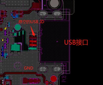
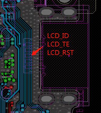
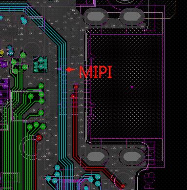
2. At levels L3 and L6, next to USB interface, there are sensitive signals associated with screen.
The floating identification pin is a well-known threat. If static electricity accumulates to a certain extent, it will definitely discharge environment, and secondary discharge power is even greater.
There are sensitive signals around USB. When an electrostatic discharge is applied, nearby GND level locally rises, especially when USB interface shield is connected to surface layer, and there are not many vias to inner GND layer around it., which further increases local level GND which will interfere with these sensitive signals resulting in crashes, black screens and flickering.
[Solution]
Fixed PIN and USB GND PIN should only be connected to main GND, not each layer to GND. MIPI, LCD_TE, LCD_RST away from USB interface.
Smartwatch screen is facing downwards and screen will turn black after opening case
This is SPI interface display screen, problem is relatively simple, a random possibility found that in SPI signal, CS line is forced to be lowered by software, and it is always in a low state, which is unacceptable.
The actual measurement changed behavior of CS line to match SPI protocol, and only lowered it when transmitting data, and black screen problem was solved.
If your smartwatch is supplied with -8 kV static electricity on USB GND pin, it is very likely to shut down
I first analyzed log, but found no clues.
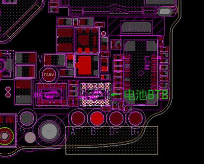
Directly disassemble whole machine, inject ESD into GND of different places on motherboard, count number of disconnections, and derive a simple rule, only in a place close to BTB battery, there will be a high probability In this case, preliminary judgment: ESD interferes with signal around batteries.
The signals around BTB battery include D+, D-, VBUS, MIPI, BAT_ID, BAT_THERM, etc. Two levels of ESD are added to these signals one after other, for example ±2 kV. Some signals may damage PMU and some will cause a crash. Only BAT_ID signal will turn off.
There are two options for shutting down: first, internal software process stops, and second, battery suddenly runs out. Especially second is often easily overlooked. Because in some cases, two shots of ESD are introduced and shutdown phenomenon immediately occurs, which is very similar to loss of a battery.
There are two options for battery power failure. One is that protection mechanism of battery protection board trips and cuts off power supply. Secondly, path from Vbat to PMU is interrupted. After checking components on motherboard, Vbat path goes through some analog components, so chance is relatively low.
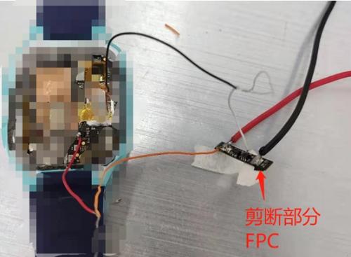
We directly connect free VBAT wire of main board to software controlled power supply, and when we press ESD again, we find that it does not turn off. It also shows that when an electrostatic discharge is introduced, battery itself has no voltage output.
The schematic of the battery protection board looks like this:
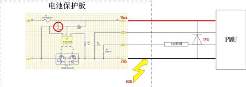
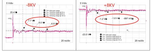
Apply +8 kV to GND in figure, no problem, because TVS on right side absorbs most of power due to forward conduction, clamp voltage is low (less than 4.4 V), and battery protection board does not activate protection mechanism. But if -8kV is input, TVS tube starts to clamp in reverse direction, and instantaneous clamp voltage is high (more than 4.4V) exceeding battery protection voltage, battery protection mechanism is triggered, and U2 MOS tube is turned off, resulting in a shutdown. The figure below shows clamping characteristics of the TVS tube, which can also confirm this conclusion.
Note that protection chip of battery protection board evaluates voltage at both ends of C1 to determine if it is protected. So, to solve this problem, it is necessary to increase capacitance of C1. The actual measurement increases C1 to 1uF and chance of tripping is greatly reduced.
Reduced, but did not completely solve problem, there must be other reasons. This reason is first guessed and then tested and verified.
As mentioned above, only BAT_ID signal will turn off. Thus, it is assumed that static electricity is connected to ID pin, which enters PMU and causes shutdown.
This time below is battery protection board wiring. The ID wiring has a long connection to GND. The instantaneous power on GND can be quickly connected to this line and finally fed directly to PMU.
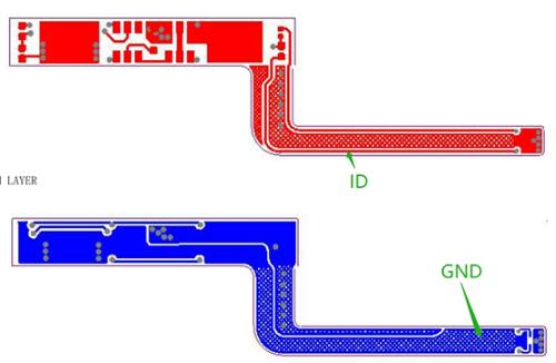
Even though there is a long connection distance between ID track and GND on motherboard, motherboard has a TVS clamp between GND and Vbat so GND voltage won't jump too much and it won't connect. a lot of energy for ID online. Conversely, GND level on FPC accumulator fluctuates most, and ID binds more power to FPC first.
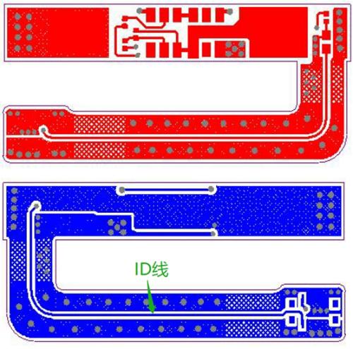
The FPC has been redesigned with following style. Basically there are no overlapping areas between ID and GND and energy will not be connected to ID pin. No more shutdown issues.
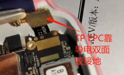
Screen is facing down, ESD hits back of case after discharge, and TP doesn't work
After inspection, it was found that TP chip was damaged. The cause of IC damage was not carefully analyzed, as it was found that double-sided adhesive for dispensing behind FPC TPU was too weak and did not stick to GND at all. TP is not properly grounded, which is causing problem.
As long as TP is well grounded, there should be no TO IC failure.
Related
- How to solve the problem with electrostatic discharge? Use several real cases to conduct a joint analysis
- What is three anti-paint? How to use it correctly?
- Three circuit diagrams to teach you how to understand how a buck RC works
- How to effectively use an oscilloscope? Even senior engineers overlook these details...
- Do you know four magical ways to use a digital multimeter?
- How to design a triode amplifier circuit
- How many of these free and easy to use circuit design programs have you used?
- How to choose a suitable power chip, do you know this?
- When designing a power supply, how to consider choice of topology?
- Several Effective Circuit Analysis Techniques
Hot Posts
 How to distinguish induction from leakage, we will teach you three tricks! Ordinary people can also learn super practical
- What is drowning in gold? Why Shen Jin?
- This is a metaphor for EMI/EMS/EMC that can be understood at a glance.
- How many types of pads have you seen in PCB design?
- Summary of Common PCB Repair Techniques
- What is three anti-paint? How to use it correctly?
- Knowing these rules, you will not get confused looking at circuit diagram.
- How to make anti-interference PCB design?
- Can diodes do this?