Location:Home Page > Archive Archive
Ever thought that diodes could still be used in this way?
2023-05-06【Archive】
Using unidirectional conduction of diodes, you can create fun and practical circuits.
This article will analyze how clipping circuit and clipping circuit are implemented with diodes.
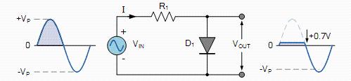
Limiter Schematic
As shown in figure below, when VIN is greater than or equal to 0.7V in positive half cycle, diode operates in forward direction. At this point, VOUT will be fixed at 0.7V.
When VIN is less than 0.7V, diode is in a cutoff state. In negative half cycle, current is reversed and diode is also in cutoff state. At this time, VOUT= VIN, and waveform of VOUT follows VIN.
Scheme of radiation limiting circuit
According to principle of radiation limiting circuit described above, following two-way radiation limiting circuit can be designed.
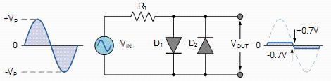
Schematic diagram of a two-way radiation limiting circuit
However, sometimes 0.7V voltage is not adequate, so how can another clipping voltage be generated? A bias voltage VBIAS is added to circuit and diode can only be turned on when VIN is greater than or equal to VBIAS. At this time, VOUT is fixed and its value is 0.7V + VBIAS, as shown in figure below.
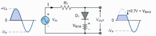
Displacement limiter circuit diagram
Clamp Outline
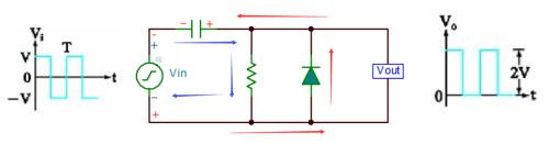
The following is a clipping circuit implemented by a diode in combination with a capacitor. The conduction voltage drop of diode is ignored in analysis, assuming that time constant RC is large enough that output waveform is not distorted.
(1) Closing principle
When input value Vin is negative in negative half cycle, current is indicated by red arrow in figure below. The diode turns on and capacitor gradually charges up to V, during which Vout=0.
When Vin input is positive in positive half cycle, current is indicated by blue arrow. The diode turns off and Vout equals voltage across capacitor plus positive half-cycle voltage V, and at this time Vout=2V.
 Clamping chain principle
(2) Bias Limiting Circuit
Similar to limiter circuit, in order to obtain required clamping value, a bias voltage must be added to circuit, as shown in figure below.
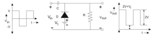
Displacement limiting scheme
When applied bias voltage matches conduction direction of diode, clamp value will be increased by V1, Vout=2V+V1.
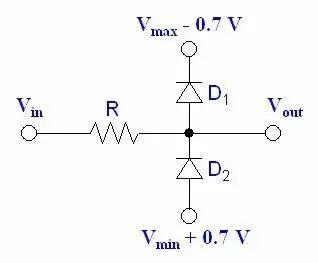
(3)Application example of bi-directional diode clamp
Some circuits use clamping effect of two diodes for protection, as shown in figure below, assuming that 0.7V corresponds to conduction voltage of D1 and D2.
Vin is greater than or equal to Vmax, D1 is enabled, and Vout will be fixed at Vmax.
When Vin is less than or equal to Vmin, Vout is fixed at Vmin.
Diode Clamp Protection Circuit
Related
- Ever thought that diodes could still be used in this way?
- It suddenly dawned on me that a 0 ohm resistor can still be used like this
- The SD card is broken, can it be fixed this way?
- Countdown of 8 most commonly used diodes
- Can diodes do this?
- List of commonly used circuits for zener diodes
- This is a metaphor for EMI/EMS/EMC that can be understood at a glance.
- Commonly used models of rectifier diodes, what are important parameters?
- Engineer Daniel tells you: The "Y Capacitor" of a switching power supply is calculated in this way.
- Count 8 most commonly used diodes! How much do you know?
Hot Posts
 How to distinguish induction from leakage, we will teach you three tricks! Ordinary people can also learn super practical
- What is drowning in gold? Why Shen Jin?
- This is a metaphor for EMI/EMS/EMC that can be understood at a glance.
- How many types of pads have you seen in PCB design?
- Summary of Common PCB Repair Techniques
- What is three anti-paint? How to use it correctly?
- Knowing these rules, you will not get confused looking at circuit diagram.
- How to make anti-interference PCB design?
- Can diodes do this?