Location:Home Page > Archive Archive
(Dry goods exchange) A detailed explanation of a simple differential amplifier circuit
2023-12-01【Archive】
The circuits in an integrated circuit are biased from various DC sources. The current in bias circuit is constant and all sizing calculations are based on this constant current.
1. Mirror DC Power

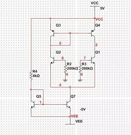
Detailed explanation of a simple differential amplifier circuit
So how this circuit works, tutorial introduction:
The Vcc power supply generates a reference current Iref through resistors R1 and Q2 and then receives corresponding Ic1 at collector of Q1 through mirror current source as a bias current to amplifier.
Ib1=Ib2=Ib
Ic1=Ic2=Ic
═〉Ic1 =Ic2=Iref-2Ib=Iref-2(Ic2/β)
Get: Ic2≈Iref×[1 &pide;﹙1+2/β﹚]
When β>>2 available:
Ic2≈Iref=[Vcc-Ube1]&pide;R
Because output DC current Ic2 is basically same as reference current, they are like a mirror image, so this DC circuit is called a mirror current source.
But I personally think that understanding from static formulas is not as effective as understanding from dynamics, which will explain problem more clearly.
When Vcc power supply is turned on, voltage is applied to base of Q2 and Q1 to generate Ib2, Ib1, and also to generate Ic2 and Ib1.
Ic=βIb, Ic2 flows through resistor R1 causing voltage drop. Once voltage drop exceeds 4.3V, voltage added to Q2 and base of Q1 will be less than 0.7V.
At this time, voltage between base emitters is not enough to overcome internal electric field of PN junction between base emitters, and Ib2 and Ib1 will become smaller, causing Ic2 and IC1 to become smaller, and voltage drop of R1 will also become smaller.
The base voltage starts rising again, causing Ib2 and Ib1 to increase again and Ic2 and Ic1 to increase. In this cycle, voltage between base and emitter reaches dynamic balance with small fluctuations of about 0.7V, and it is stable from a static point of view. At 0.7V.
2. Amplifier Analysis
Since entire analysis is about this DC bias current, we must first calculate current for this mirror current. All our calculations are based on symmetrical circuit structure and matched triode parameters.
Q5 and Q7 form mirror flow, IC5=IC7=(Vcc-Vee-Vbe5)/R4=(10v-0.8v)/4000Ω=2.3mA, error is about 2Ib5 or 2Ib7, you can also see Q5 from The collector current of IC7 shunts Ib5 and Ib7, Ib5=Ib7, so it is 2Ib5 or 2Ib7.

The simulated value is 2.26 mA, which is basically same.
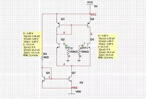
The collector of Q7 is connected to emitter of Q1 and Q2, then IC7=2*Ie1=2*Ie2, Ib1=Ib2=Ie1/(1+β)=Ie2/(1+β), this virtual triode β value is predicted to be 100, Ib1=Ib2=(1/2*IC7)/(1+100)=11.3 uA. Detailed explanation of a simple differential amplifier circuit as shown in figure
The simulated value is 11.3µA, stable.
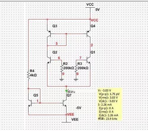
Knowing base currents of Q1 and Q2, we can calculate collector potential of Q7. If we choose two balancing resistors R2 and R3 Q1 and Q2, resistance value of R3 will be 200 kΩ, and collector potential of Q7 Vc7= 0V-R2*Ib2-Vbe2 \u003d 0V-R3 * Ib1-Vbe1 \u003d 0V-200k * 11.3 μA-0.8V \u003d -3.06V. As shown
The simulated value is -3.03V, which is basically same.
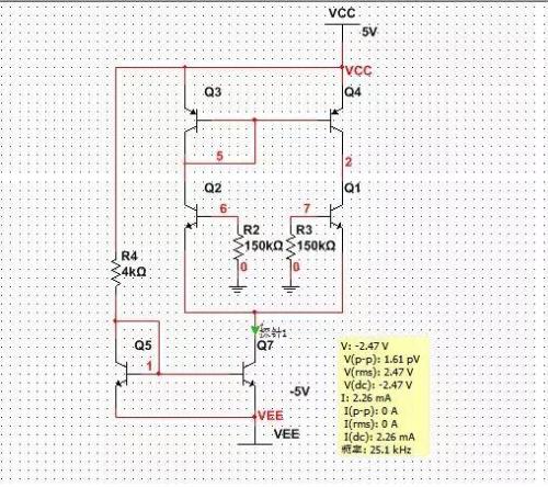
If we select R2, R3 is 150kΩ, then collector potential is Vc7=-2.5V (calculated as above). Detailed explanation of a simple differential amplifier circuit as shown in figure
The simulated value is -2.47, which is basically same.
Then explain problem, choice of base balance resistance of amplifier tubes Q1 and Q2 directly affects collector potential of Q7, that is, emitter potential of Q1 and Q2, if emitter potential of Q1 and Q2 is too high, this will affect gain dynamic range of amplification circuit. This a place to pay attention to, and this is also disadvantage of this simple differential amplifier.
Q3 and Q4 form a mirror current source for amplifying transistors Q1 and Q2 as active collector loads. Q3 and Q4 are connected to collectors of lamps of amplifier Q1 and Q2, then IC3=IC4=IC3=IC4. Collector potential Q2 VC2=5V-Vbe2=5v-0.7v=4.3v.
As in above analysis of image current, collector current of IC3 Q3 and collector current of IC4 Q4 also have a small error, error is 2Ib3 or 2Ib4, this error current will flow to next stage circuit or load,< /p>
Let's add a resistive load R1 with a nominal value of 5 kOhm to circuit. We connect this resistor to ground, which is 0 V, then we can roughly determine collector of Q1. Earlier we said that collector current of triode is constant. Yes, voltage is determined by external parameters, and we know that error current flowing through R1 is very small. The more symmetrical circuit, smaller error current. The ideal static situation is that no current flows through R1, but it actually impossible We can only control that error is very small.
A very small error current flows through R1 to ground (0V), and resulting voltage drop is also very small. The collector voltage of Q1 is also basically 0V, and error at 0V is very small, as shown in figure. a detailed explanation of a simple differential amplifier circuit
The simulated value is -109mV and deviation from ground (0V) is very small. The more symmetrical circuit, smaller deviation.
Because error current flowing through R1 is very small, no matter how resistance of R1 changes, resulting voltage drop is very small. The collector potential of Vc1 Q1 is close to 0V, and deviation from 0V is small, as a simple difference is shown Detailed explanation of amplifier circuit
We changed R1 to 1 kΩ and 10 kΩ respectively, and simulated Q1 collector potential Vc1 was -21.9 mV and 219 mV, and deviation from 0 V was very small.
Related
- (Dry goods exchange) A detailed explanation of a simple differential amplifier circuit
- (Dry goods exchange) Four parts of operational amplifier circuit
- The composition of switching power supply circuit and a detailed explanation of general circuits
- (Exchange of haberdashery) Analysis of principle of differential circuit
- (Dry goods exchange) Power principle analysis, waveform analysis, voltage calculation, circuit diagram
- (Dry goods exchange) Eight basic circuits of analog circuits
- (Dry goods exchange) Calculation of air gap by formula of transformer
- Detailed explanation of working principle of TTL gate circuit
- A detailed explanation of three commonly used LED drive power schemes.
- What is a delay scheme? Explanation of 6 Kinds of Delay Circuit Principles
Hot Posts
 How to distinguish induction from leakage, we will teach you three tricks! Ordinary people can also learn super practical
- What is drowning in gold? Why Shen Jin?
- This is a metaphor for EMI/EMS/EMC that can be understood at a glance.
- How many types of pads have you seen in PCB design?
- Summary of Common PCB Repair Techniques
- What is three anti-paint? How to use it correctly?
- Knowing these rules, you will not get confused looking at circuit diagram.
- How to make anti-interference PCB design?
- Can diodes do this?