Location:Home Page > Archive Archive
Understand Current Detection Circuit in One Article
2023-03-18【Archive】
Apply current detection
Circuit detection circuit is often used in: high voltage short circuit protection, motor control, DC/DC converter, system power control, secondary battery current control, battery control and other current detection scenarios.
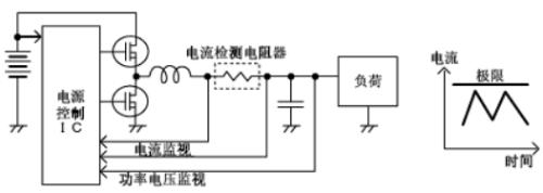
In most applications, current is measured by voltage drop across a sense resistor.
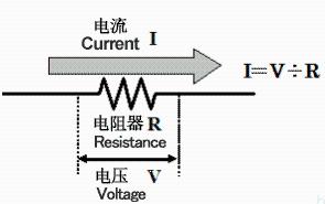
Generally, when passing current, a resistance value with a voltage drop of tens of mV to hundreds of mV is used, and a low resistance value below a few ohms is used for low resistance to detect current; a few mΩ is required to detect large currents in tens of A. Therefore, low resistance metal plate and metal foil resistors are more commonly used, which are known for their low resistance values, and small currents are detected using relatively large resistance values ranging from hundreds of mΩ to several ohms. .
When measuring current in a circuit, there are usually two places where resistors are placed. The first place is between power supply and load. This measurement method is called high-side measurement. The second place where sense resistor is usually placed is between load and ground. This current measurement method is called low side current measurement.
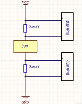
Both measurement methods have their pros and cons. Resistors on low voltage side add unwanted extra impedance to ground path; circuits using high-side resistors must be able to handle relatively large common-mode signals. One of advantages of measuring low side current is that common mode voltage, i.e. average voltage at measurement input, is close to zero. This simplifies design of application circuits and selection of devices suitable for this measurement. The current measurement circuits on underside measure voltage close to ground, which is preferred method of current measurement when working with very high voltages or in applications where supply voltage may be subject to voltage spikes or spikes. Because current measurement on low voltage side can withstand interference from high voltage surges and can monitor current in high voltage system.
Current detection circuit
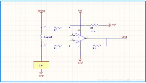
1. Bottom side detection
The main disadvantage of low side current measurement is that voltage drop across sense resistor will be different when using power supply ground, load ground, and system ground. Problems can arise if other circuits are connected to power supply ground. To minimize this problem, all interacting circuits should be tied to same ground, and reducing value of current sense resistor can help minimize ground drift.
As shown in figure above, if GND pin of op-amp in figure refers to positive terminal of RSENSE, then its common-mode input range must be below zero, that is, GND - (RSENSE × LOAD). Rsensor shares ground (GND).
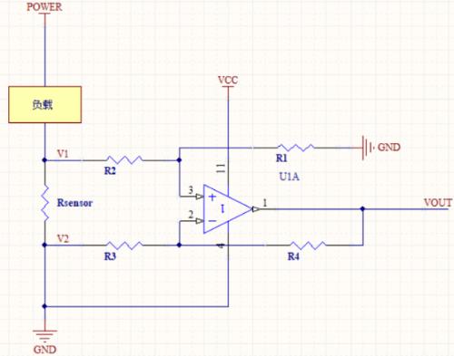
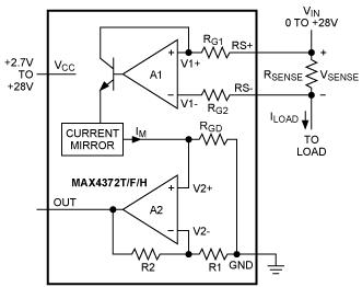
2. High side detection
With advent of a large number of ICs containing high-precision amplifiers and precision-matched resistors, it has become very convenient to use differential amplifiers to measure current on high voltage side. High-side detection led to development of current detection IC, which reduced problems of changing parameters and too many devices caused by discrete devices. Integrated circuits are convenient for us to use. The figure below shows IC solution for upper arm detection:
How to connect detection circuit
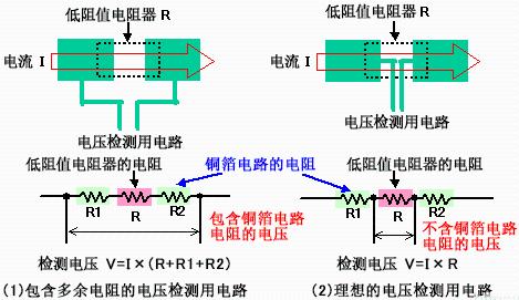
To detect voltage drop when current flows through a resistor, you need to draw circuits to detect voltage at both ends of resistor. The voltage detection connection is shown in Figure (2) below, and it is recommended that it be routed from inner center of electrode pad of resistor. This is because copper foil pattern on PCB also has a small resistance value, and it is necessary to avoid influence of voltage drop caused by resistance value of copper foil pattern.
If voltage detection circuit is drawn from side of electrode pad as shown in Figure (1) below, detection object will be resistance value of low resistor plus voltage drop of copper resistance value. foil pattern, and the current cannot be correctly detected.
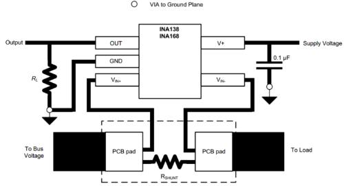
PCB layout guide:
Related
- Understand Current Detection Circuit in One Article
- Why do diodes conduct electricity in one direction? understand in seconds
- Is printed circuit board covered with copper very “up to mark”? One article to help you get practical guidelines and norms
- An article to understand "advantages" and "cons" of solid capacitors
- One Article for Understanding PFC (Power Factor Correction)
- Diode switching circuit and troubleshooting, one complete wizard
- One article eats up all rectifier and filter circuits
- You will understand difference between input impedance and output impedance after reading this article!
- You will understand difference between input impedance and output impedance by reading this article.
- Three circuit diagrams to teach you how to understand how a buck RC works
Hot Posts
 How to distinguish induction from leakage, we will teach you three tricks! Ordinary people can also learn super practical
- What is drowning in gold? Why Shen Jin?
- This is a metaphor for EMI/EMS/EMC that can be understood at a glance.
- How many types of pads have you seen in PCB design?
- Summary of Common PCB Repair Techniques
- What is three anti-paint? How to use it correctly?
- Knowing these rules, you will not get confused looking at circuit diagram.
- How to make anti-interference PCB design?
- Can diodes do this?