Location:Home Page > Archive Archive
How did BUCK scheme come about? Application: 3 kinds of evolutionary chains
2023-03-18【Archive】
Baka's origins
I don't want to talk more about development history of power electronics. After decades of development, from initial low efficiency and high volume linear power supply to current high frequency, small volume and high efficiency. The following will describe how Buck converter, one of three main topologies, has evolved.
Anyone who has studied electronics should know that easiest way to get desired voltage (low) from voltage (high) is probably to divide the voltage with resistors, as shown below.
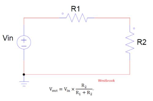
This method is most convenient and fastest, and currently general voltage selection mostly uses this method, but what if power is a little more? Since R1 and R2 are connected in series, losses in R1 cannot be neglected. If required voltage is much lower than input voltage, efficiency of circuit will be extremely low. Try warping circuit by replacing R1 with a triode, which is current LDO model, as follows:
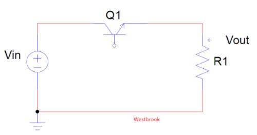
Due to modification, initial losses on R1 are transferred to transistor Q1. Since Q1 carries voltage difference between input and output, efficiency of circuit is relatively low. To improve efficiency, triode used to work in a linear state, can it be put into a switching state? In this way, triode only has switching losses and conduction losses, so losses will be greatly reduced. Can be changed to following scheme:
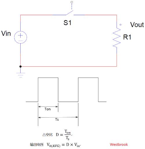
The duty cycle of this circuit is Ts and conduction time is Ton, so duty cycle is D=Ton/Ts, but output voltage is closely related to state of switch. When S1 is on, there is output voltage, and when S1 is off, there is no output voltage, but output load always requires a continuous supply of power, which is unacceptable for output load. This requires decoupling, and capacitor of energy storage component is inserted at a certain position of converter, so that even when input terminal S1 is turned off, output capacitor can continue to output power to ensure stability of output voltage.
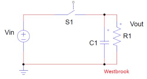
Have you seen effect of this? Since capacitor voltage cannot change dramatically when S1 is closed, a very large inrush current will be generated in line, which will not only cause noise and EMI problems, but S1 may be damaged at this time. Therefore, it is necessary to limit current as follows:
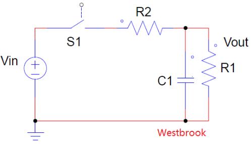 After adding a current limiting resistor R2, there will not be as much inrush current at moment S1 closes, but since R2 is in series with main power circuit, resistor will consume power, so that reduced power consumption on switch may decrease over time, dissipated in additional resistor. Therefore, in order to maximize efficiency, R2 can be converted into a reactance element. Basically, reactance element only stores energy and does not consume energy. As we all know, current at both ends of inductor cannot change suddenly, so when switch S1 is closed , inductor can suppress inrush current very well without power consumption. As shown below:
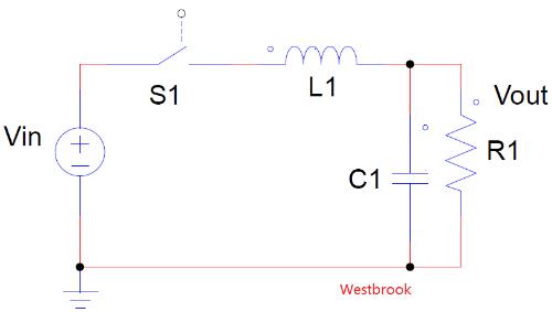 This eliminates inrush current caused by C1 action when S1 is closed, but what about when S1 is off? As just mentioned, current at both ends of an inductor cannot change suddenly. When S1 suddenly turns off, this is equivalent to a sudden change in current of inductor. will be consumed in form of an "arc", which creates a very large voltage spike. Therefore, in order to make inductor L1 free-wheeling, it is necessary to add a flyback diode as follows:
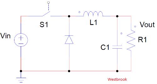
So when S1 suddenly turns off, L1's energy will continue to flow through diode, which is why we also call it a freewheeling diode. Of course, to improve efficiency, freewheeling diode can be replaced with a MOSFET as follows:
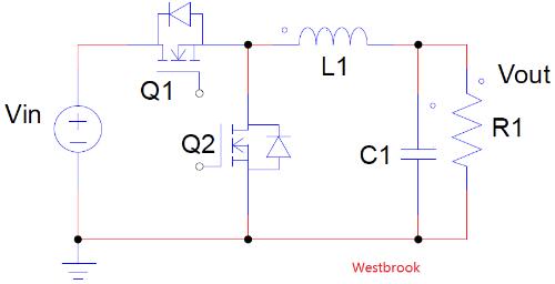
Such a synchronous buck converter is available. The inductor can be placed in different positions and converted into different layouts. By placing it at input, you get a boost converter, and at bottom you get a buck-boost converter. Therefore, only these three main converters exist, and many other topologies are developments of these three main converters.
For example, forward is an isolated version of Buck, and backtravel is an isolated version of Buck-boost.
Related
- How did BUCK scheme come about? Application: 3 kinds of evolutionary chains
- What is a delay scheme? Explanation of 6 Kinds of Delay Circuit Principles
- Three circuit diagrams to teach you how to understand how a buck RC works
- Principal analysis of BUCK / BOOST circuit, a summary is also in place
- Did you pay attention to details of using relay?
- Explain in detail difference and application of two-three-four-wire system.
- Hear how engineers talk about various "fantasies" about first power-up on PCB.
- Sample Analysis! Tell us about the skills of triode amplifier circuitry.
- Great God: The scheme is calculated
- PTC Thermistor Application Example
Hot Posts
 How to distinguish induction from leakage, we will teach you three tricks! Ordinary people can also learn super practical
- What is drowning in gold? Why Shen Jin?
- This is a metaphor for EMI/EMS/EMC that can be understood at a glance.
- How many types of pads have you seen in PCB design?
- Summary of Common PCB Repair Techniques
- What is three anti-paint? How to use it correctly?
- Knowing these rules, you will not get confused looking at circuit diagram.
- How to make anti-interference PCB design?
- Can diodes do this?