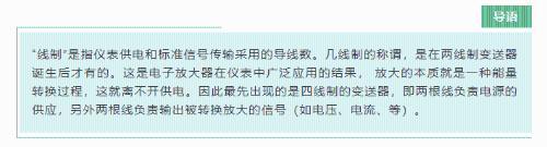
Location:Home Page > Archive Archive
Explain in detail difference and application of two-three-four-wire system.
2023-03-18【Archive】
A 220 VAC instrument must be a four-wire system
A four-wire signal device means that power circuit and signal circuit are independent, separated by an isolating circuit, and used to isolate a standard 4-20mA signal. So signal must be isolated and not normally grounded. The power supply can be 24V DC or 220V AC.
When power provided by a 2-wire system is not sufficient to power instrument, a 3-wire system with a standard 4~20mA signal is used.
Three lines of a 3-wire system: one power line (typically 24VDC+), one signal line, and one common power and signal line, which is used for voltage and current reference point. a loop.
Standard signal other than 4~20mA is not called 2-wire system
The 2-wire system is designed to carry a standard 4~20mA signal when powered by two wires. Signals other than this standard are not called two-wire systems. The minimum power supply for a two-wire system is: 4 mA×24 V - power consumption of receiving device - line losses.
So, what are main methods of powering four-wire, three-wire and two-wire systems in real field conditions?
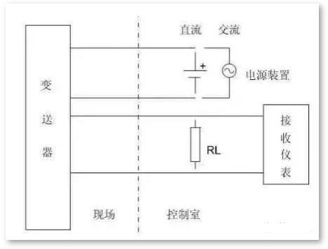
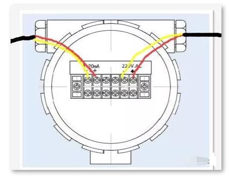
Most of 4-wire power supply is 220 VAC and some is 24 VDC.
A four-wire transmitter is shown in figure below, most of its power supply is 220V AC and part is 24V DC. Output signal 4-20mA DC, load resistance 250Ω or 0-10mA DC, load resistance 0-1.5kΩ, some also have mA and mV signals, but load resistance or input resistance is different due to shape output circuit A values are different.
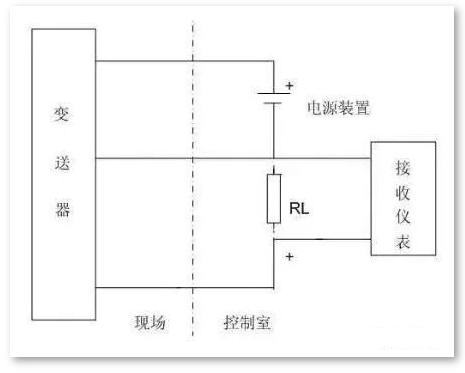
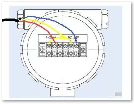
Three-wire power supply mainly 24 VDC
A three-wire transmitter is shown in figure below. The so-called three-wire system means that one wire is used for positive end of power supply, other wire is used for positive end of output signal. , and one wire is used for negative end of power supply and negative end of signal. Most of its power supply is 24V DC, output signal is 4-20mA DC, load resistance is 250Ω or 0-10mA DC, and load resistance is 0-1.5kΩ, some also have mA signals and mV, but load resistance or input resistors have different values depending on shape of output circuit.
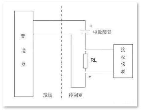
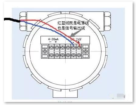
2-wire 24 VDC power supply current
The two-wire transmitter is shown in figure below, power supply is 24VDC, output signal is 4-20mADC, load resistance is 250Ω, potential of negative line of power supply is 24V. is lowest, this is common signal line, for intelligent transmitter, you can also load FSK keying signal of HART protocol into a 4-20 mA DC signal.
Due to different operating principles and designs of different transmitters, different products have emerged that also define two-wire, three-wire, and four-wire transmitter connection schemes. How to choose four-wire, three-wire and two-wire devices?
When power exceeds 10W and accuracy requirements are high, a four-wire instrument is usually used
The application of four-wire system instrument began with appearance of DDZ-II type electric block combination instrument, 220VAC power supply, and four-wire system converter, followed by 0~10mA.DC output signal, application is widely used. Due to complex conversion circuits and high power consumption, many instruments still prefer to use four-wire systems. The most common ones, such as Coriolis mass flowmeters and electromagnetic flowmeters, are still four-wire systems, because mass flowmeters require operation with vibration. The electromagnetic flow meter requires excitation power input, and power of two flow meters exceeds 10W, so a four-wire system is required.
Reduce unsafe supply voltage, generally use a 3-wire device
In order to apply three-wire system, in order to match power supply design required by instrument, inverter power supply is changed from 220V AC to low voltage DC power supply. taken from the 24 VDC power supply, unsafe supply voltage is reduced. Thus, there are three-wire transmitters.
The power is small and economical, two-wire system is usually used
The application of two-wire system instrument accepts DC 4-20mA signal, and field instrument can realize two-wire system. At present, domestic two-wire system transmitters are widely used.
Summarizing, for user, choice should be based on actual position of device, such as signal system unification, explosion protection requirements, receiving equipment requirements, investment and other issues, in order to comprehensively consider choice.
It should be noted that 4-20mA DC output signal of three-wire and four-wire transmitters is different from two-wire system in principle and output circuit structure, so output negative terminal may need to pay attention to whether it is connected to negative line of power supply 24 In or whether he can share land. If necessary, isolation measures can be taken, such as power distributors, safety barriers, etc., to share power and ground with other appliances and avoid additional interference. .
Related
- Explain in detail difference and application of two-three-four-wire system.
- Explain in detail classification of more than a dozen types of "recommended collection" capacitors
- Explain PCB copy process in detail, it's amazing
- Circuit Analysis of 6 Examples Explaining Lightning Surge Protection in Detail
- Why are there always two capacitors in circuit 0.1uF and 0.01uF?
- Why always put two 0.1uF and 0.01uF capacitors in the circuit?
- Four ways to reduce the output "ripple and noise" of a switching power supply
- Optocoupler and application circuit
- Experience in recognition of circuit diagrams of electronic circuits and method of circuit analysis
- The role of polar and non-polar capacitors in parallel connection
Hot Posts
 How to distinguish induction from leakage, we will teach you three tricks! Ordinary people can also learn super practical
- What is drowning in gold? Why Shen Jin?
- This is a metaphor for EMI/EMS/EMC that can be understood at a glance.
- How many types of pads have you seen in PCB design?
- Summary of Common PCB Repair Techniques
- What is three anti-paint? How to use it correctly?
- Knowing these rules, you will not get confused looking at circuit diagram.
- How to make anti-interference PCB design?
- Can diodes do this?