Location:Home Page > Archive Archive
Relay selection skills
2023-03-18【Archive】
As for a relay, you may know that it is equivalent to a switch, and principle is actually very simple. But there is still a lot of learning when it is actually used. The following content is explained in detail and I will share it with you hoping to be helpful to you.
See Table 1 for relay selection principles. After confirming items marked with "" in "to be specified" column in table, relay can be selected. If there are additional requirements, it is necessary to further consider relevant items marked with a "" in "Reference" column.
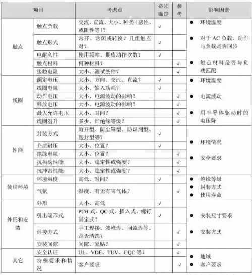
Table 1
More about table
1. Contact
1.1 Contact load
When determining whether load that relay can handle meets requirements of application, in addition to determining size of load, it is also necessary to determine type of actual load, since different loads have different steady states. See table 2 for values. Unless otherwise noted, loads listed in general specification are resistive loads.
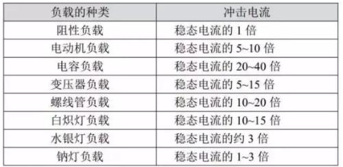
Table 2
Shows representative load versus starting current and time. In addition, depending on polarity of moving and static contacts of relay, this will also affect electrical durability.
1.2 Contact material. See Table 3.
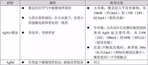
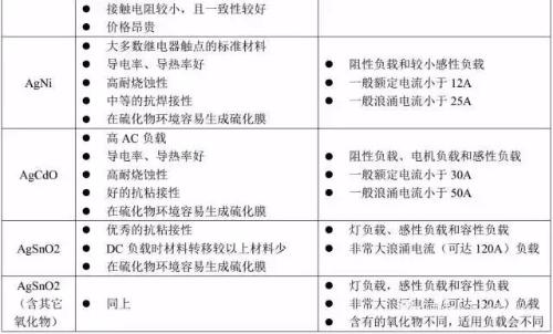
Table 3
Notes:
(1) Each relay must take into account maximum current specified in instruction manual.
(2) If general conditions permit, it is best to test against actual usage.
(3) The gold-plated contact layer performs better under medium to light loads. But for a load, it is usually only used to maintain initial performance of contacts before using relay.
1.3 Electrical resistance
Unless otherwise stated, electrical endurance given in general guide is nominal value measured at rated load, specific temperature, load factor and operating frequency, so electrical endurance will be different for other load types and switching frequencies. Generally, for loads above 2A, electrical endurance of same relay with solder protection and dust cover is higher than that of a relay with plastic seal, so try to use a relay with solder protection and dust cover. switch with a protective cover, as far as environment allows. Increase life of relay.
2. Coil
2.1 Voltage
For a relay to operate reliably, it must be ensured that operating circuit can supply rated voltage to relay coil. When using a transistor to drive a relay, since inherent voltage drop of transistor itself will cause voltage applied to relay coil to be lower than rating of control circuit, it is recommended to use a 4.5V relay when voltage of transistor control circuit is 5V. Sometimes, to shorten time of relay, it is possible to apply maximum allowable voltage to coil in a short time, but at same time it is necessary to ensure that relay does not overheat and even fail. For polarized relays, check polarity of coil voltage.
2.2 Coil resistance
In order for a relay to work reliably, it must be ensured that operating circuit can supply coil's rated power input to relay, so an appropriate coil resistance must be selected.
3. Performance
3.1 Encapsulation method
In order to ensure reliability of relay, different packaging methods have different post-processing requirements for relay, see Table 4
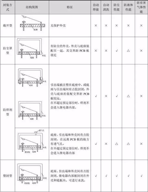
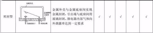
Table 4
Notes:
(1) "√": good; "×": bad; "△": attention;
(2) Since plastic has a certain air permeability, please use sealed relay if there is harmful gas or explosion proof is required.
4. Use environment
4.1 In an environment with high humidity, even condensation and a lot of dust, it is recommended to use a relay in a plastic case, because high humidity can easily accelerate corrosion of relay structural parts, and dust can easily cause relay contacts. fail.
In an environment containing silicone, it is recommended to use sealed products, as silicone will accelerate failure of relay. In an environment containing harmful gases such as H2S, SO2, NO2, etc., solder-resistant and dust-proof type cannot be used, and plastic seal type can be used, and test is confirmed by actual use. . In real world, if ambient atmosphere is better, it is recommended to use dust-tight or solder-resistant relays, because dust-tight or solder-tight relays may have a longer electrical life than plastic-sealed relays.
5. Appearance and installation
5.1 Choice of soldering method Lead-free relay terminals Recommended soldering temperature and time: 240℃~260℃, 2s-5s. If reflow soldering is required, confirm if manual states that relay can be reflow soldered.
5.2 The output form allows you to select appropriate output form (table 6) and installation method (table 7) depending on actual situation
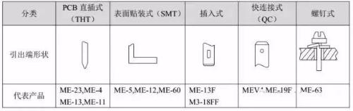
Table 6
Table 7
6. Other
6.1 Safety Certification General UL/CUL certification is applicable to North America, VDE and TüV certification is applicable to Europe, but due to international authority of these certifications, most other countries also recognize these certifications.
Relay Precautions
1. Try square wave control for DC relay and sinusoidal control for AC relay.
2. To keep relay in good working order, be careful not to drop relay or subject it to strong impacts. It is not recommended to use a dropped relay.
3. Try to use relay in an environment with normal temperature and humidity, less dust and harmful gases. Harmful gases include gases containing sulfur, silicon and nitrogen oxides.
4. For a magnetic latching relay, it must be set to active or reset position, as appropriate, before use. Pay attention to polarity and pulse width when applying voltage to coil.
5. For polarized relays, pay attention to polarity of coil voltage (+, -). In addition, there are other precautions that will be explained in order in order of "Table 1 Relay Selection Principles".
6. At same current, direct current (DC) voltage value that relay can reliably switch is much lower than alternating current (AC) voltage value, because alternating current has a zero point (the point where current is zero), and generated arc is easily extinguished. For DC, generated arc can only be extinguished after gap between contacts reaches a certain value, which makes arc duration longer than AC, which increases contact consumption and material transfer.
7. When relay contact action is synchronized with AC phase of switched load, if contact is always connected or disconnected when load voltage is high, as shown in Figure 2, it will increase connection or transfer contact of contact material, resulting in premature failure of the relay, please make sure that it is a hysteretic random on and off phase in actual use.
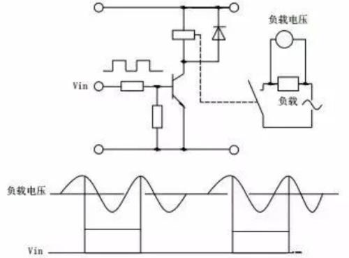
Picture 2
8. Connection between multiple sets of contacts and a load If there are multiple sets of contacts, place contacts as close as possible to one pole of power supply and load to other pole of power supply. supply, as shown in Fig. 3(a), which can prevent occurrence of a voltage difference between contacts and possibility of a short circuit between contacts. Avoid edge joins as shown in fig. 3(b).
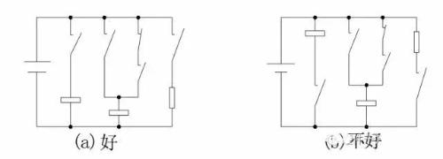
Picture 3
9. The phenomenon of contact material transfer means that contact material of one side is transferred to contact of other side.
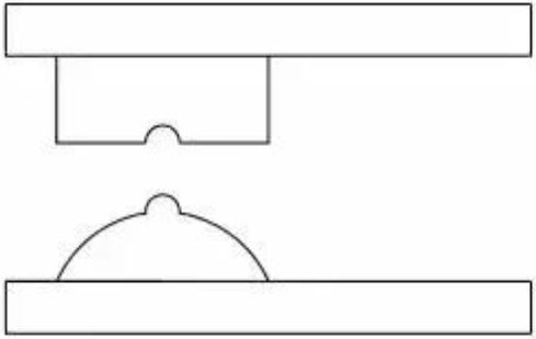
Picture 6
Typically, contact material transfer is caused by one-sided high current flow or capacitive load surge current, which occurs mainly in DC circuits and usually has form of positive convexity and negative concavity. Thus, correct use of contact protection schemes or use of AgSnO contacts with better resistance to material transfer can mitigate phenomenon of contact material transfer. For high power DC loads (from a few A to tens of A), this must be confirmed in practice.
10. In general, inductive loads are more likely to damage contacts than resistive loads. If a proper protection circuit is used, effect of inductive loads on contacts is basically same as that of resistive loads. But note that if used incorrectly, it can be counterproductive.
Table 7 is a representative example of a touch protection circuit.
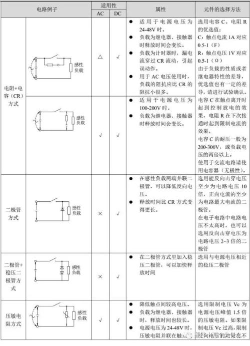
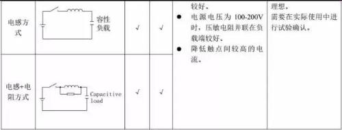
Table 7
WARNING Do not use contact protection schemes listed in Table 8.
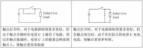
Table 8
11. When installing protective components such as diodes, C-Rs and varistors, they must be installed close to load or contacts. If distance is too long, protection effect will not be perfect. It is recommended to install within 50 cm.
12. The AC relay supply voltage preferably has a sinusoidal waveform (sine waveform), because AC coil can suppress humming sound better in case of a sinusoidal waveform, and if waveform is distorted or distorted, suppression function cannot be well reproduced. On fig. 7 shows examples of several common signals.
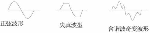
Picture 7
13. For stable operation, voltage applied to both ends of coil of DC relay, it is recommended to use rated voltage of coil with a ripple change rate of less than ±5%, otherwise relay will be unstable.
14. The maximum allowable voltage is maximum voltage that can be applied to relay coil, not value that is allowed to be applied continuously.
15. During operation of relay, coil will generate heat, raising its temperature. In general, when using impulse voltage with an on-time of less than 2 minutes, coil temperature increase is related to on-time (ON) and on-off ratio (OFF) and all kinds of relays. basically same, see table 9.
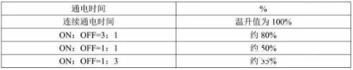
Table 9
16. When designing circuit, pay attention to avoid leakage current flowing through coil when the relay is not operating, as shown in Figure 9.
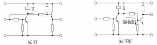
Picture 9
17. When multiple relays form a series-parallel circuit, pay attention to avoid malfunction caused by bypass current and leakage current, as shown in Figure 10
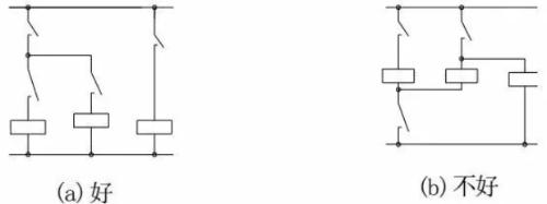
Picture 10
18. During operation of common relays, there are stages such as contact pressure change, contact vibration, and contact instability. When voltage applied to coil is gradually increased, time of this unstable stage will change. Long, affects life of relay. To minimize effect of this on relay, try to supply coil with step voltage whenever possible (using a switching circuit).
19. Please avoid using relay's own normally closed contact to disconnect its own coil, which will cause failure due to instability of relay action, as shown in Figure 11.
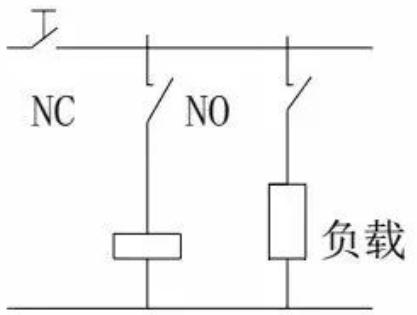
Picture 11
20. To trip or reset a latching magnetic relay, apply a rectangular rated voltage to coil that is more than 5 times trip or reset time specified in manual, and then confirm operation. If pulse width does not meet above requirements, perform a field test to confirm. Please avoid using it when power supply contains a lot of voltage surges.
21. The ideal installation method for vibration and shock protection is to make direction of action of contact and direction of action of armature at right angles to direction of vibration and shock. In particular, when coil is not energized, vibration and shock resistance of normally closed contact is weak, and its performance can be guaranteed with correct installation direction. Figure 12.
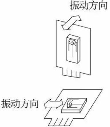
Picture 12
22. Please do not use ultrasonic cleaning to clean relay, because ultrasonic waves will cause contact shorting, coil disconnection and other malfunctions.
23. Please do not bend relay terminals during installation (as shown in Figure 13), this may damage original characteristics of relay. Please process PCB correctly according to mounting hole pattern in product manual. Make sure relay remains stationary. Note that if clamping force of mounting hook is too high, it may cause internal failure of relay.
Picture 13
24. Long Tube Packing When using a relay packed in a long tube, do not swing packing tube to hit relay, otherwise relay may malfunction. If package uses a stopper, press stopper into relay so that relay does not hang loose in packing tube. Rice. 14
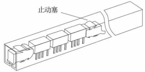
Picture 14
Related
- Relay selection skills
- Did you pay attention to details of using relay?
- 3 MOSFET device selection rules that will teach you how to become a device selection wizard
- General PCB debugging skills
- Switching Power Supply PCB Design Skills
- Welding knowledge and skills that electronics professionals need to understand
- Sample Analysis! Tell us about the skills of triode amplifier circuitry.
- You must learn drawing techniques and skills of 18 special circuit board routes.
- What skills should I pay attention to when designing a triode amplifier circuit? (Easy to understand)
Hot Posts
 How to distinguish induction from leakage, we will teach you three tricks! Ordinary people can also learn super practical
- What is drowning in gold? Why Shen Jin?
- This is a metaphor for EMI/EMS/EMC that can be understood at a glance.
- How many types of pads have you seen in PCB design?
- Summary of Common PCB Repair Techniques
- What is three anti-paint? How to use it correctly?
- Knowing these rules, you will not get confused looking at circuit diagram.
- How to make anti-interference PCB design?
- Can diodes do this?