Location:Home Page > Archive Archive
Welding knowledge and skills that electronics professionals need to understand
2023-04-02【Archive】
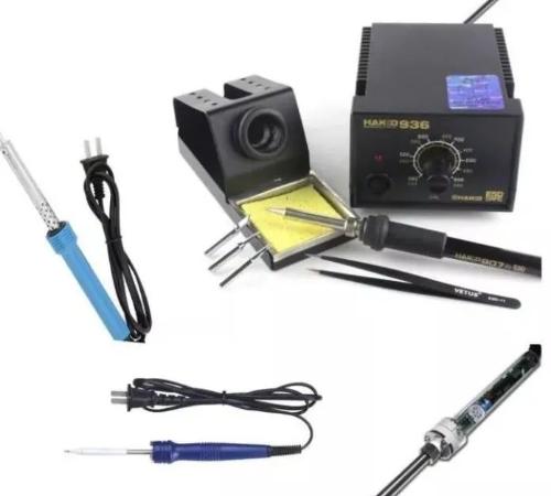
Common tools needed for soldering SMD components
Let's take a look at some of basic tools needed to solder commonly used SMD components (see Figure 1).
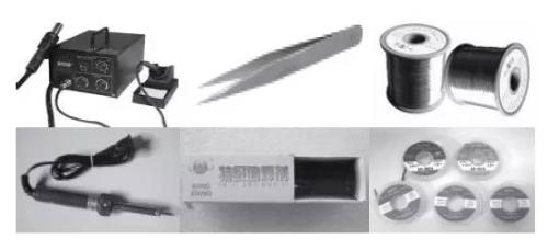 Fig. 1. Common tools used for manual soldering of patch components
1. Electric soldering ironSoldering components by hand is definitely a must. Here I recommend one with a sharper tip because it can accurately and conveniently solder one or more pins when soldering SMD chips with tight pins.
A constant temperature adjustable electric soldering iron is your best choice (temperature can be adjusted and stabilized, there are two types of single knob temperature adjustment and a soldering station).
It should be noted that above type of internal heating and external heating type usually do not have a power switch, and they heat up when plugged in, and need to be turned off to cool down.
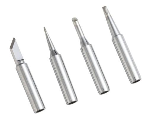
As they say, a good horse needs a good saddle. Then head of soldering iron is saddle of horse (soldering iron).
The choice of soldering iron tip should be determined depending on contact surface of object being welded.
For example, for common plug-in components, we mainly use horseshoe heads (large contact surface); small SMD components can be pointed or curved (soldering dense components); for conventional microcircuits, cutting heads (easy to mount) can be used. butt seam).
Of course, a more advanced DIY method is polishing a uniquely shaped soldering iron tip to suit your needs.
As for soldering iron we just bought, we cannot use it right away, we need to tin new soldering iron for first time.
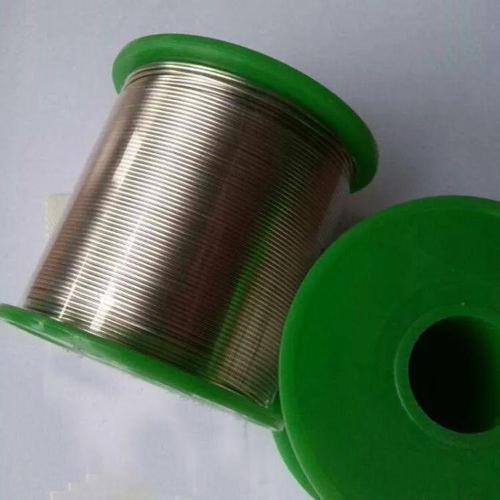
2. SolderGood solder is also very important for SMD soldering. If conditions permit, use as thin a solder as possible when soldering SMD components. Thus, it is easy to control amount of tin, so that there is no need to waste solder and absorb tin.
Chinese name: solder, solder, tin wire, tin wire, English name: solder, solder is composed of tin alloy and additives. The composition of alloy is divided into tin-lead and lead-free additives. Tin alloy middle part.
There are different additives for different types of solder. The additive is designed to improve auxiliary thermal conductivity of solder during welding, remove oxidation, reduce surface tension of material being welded, and remove oil. on surface of material to be welded and increase welding area. The characteristic feature of solder is a tin alloy wire of a certain length and diameter, which can be used in combination with an electric soldering iron or a laser when welding electronic components.
Difference between lead and lead-free solder:
1. The difference between lead and lead-free solder is only content.
2. Solder containing lead must be artificially supplemented with lead. The most famous solder ratio is tin-lead solder (national standard: tin content 63%, lead content 37%).
3. Lead-free solder wire also contains very little lead, and there is currently no completely pure metal product. Usually, lead-free solder is called lead-free solder. Lead-free solder does not mean that it does not contain lead at all. Lead-free means that lead content is relatively low, which can be roughly considered lead-free. , EU defines lead-free standards as: 1000PPm. Considering possibility of further contamination during welding and post-processing, in order to ensure that customer's finished product meets EU standard, lead content of conventional solder wire will be well below this standard.
4. Both lead-free solder wire and lead-free solder wire will cause soldering iron tip corrosion, because temperature of lead-free soldering is higher than that of lead-free soldering wire, and alloy composition is different, and lead-free solder wire is more likely to cause soldering iron corrosion Requirements for lead-free and corrosive activity, It is recommended to use a lead-free special electric soldering iron when soldering lead-free tin wire.
3. TweezersThe main function of tweezers is to conveniently pick up and place SMD components when welding. The tweezers require a sharp and flat front end to facilitate clamping of components. In addition, some ICs that need to be protected from static electricity require antistatic tweezers.
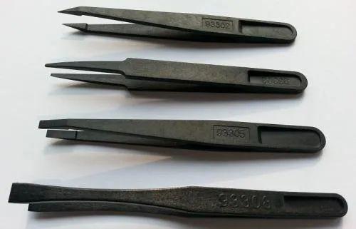
Anti-static tweezers are also called semiconductor tweezers, static conductive tweezers that can prevent static electricity. They are made of carbon fiber and special plastic, and have good elasticity.
Easy to use and durable, free of ash, acid and alkali, high temperature resistant, can avoid traditional anti-static tweezers from polluting products due to soot, suitable for production and use of precision electronic components such as semiconductors and ICs and special use.
Anti-static tweezer is made of special conductive plastic material, which has good elasticity, ease of use and static discharge, and is suitable for handling and installing static-sensitive components.
Surface resistance: 1000 kΩ - 100000 MΩ. Anti-static tweezers are suitable for production of precision electronic components, semiconductors and computer magnetic heads and other industries.
If you use carbon fiber and special plastic anti-static tweezers, they will not emit ash, acid, alkali and high temperature resistant, which can prevent soot contamination of products with traditional anti-static tweezers. .
4. Tin Absorption TapeIt is easy to get too much tin when soldering SMD components. Especially when soldering dense multi-pin SMT chips, it is easy to cause two adjacent pins or even several pins of chip to be shorted by solder. At present, traditional tin absorber is useless, and a wicker tin absorber is needed at present.
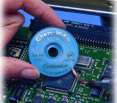
5. Rosin

Rosin is most commonly used flux in soldering because it can precipitate oxides in solder, protect solder from oxidation, and increase fluidity of solder.
When soldering in-line components, if components are rusty, scrape them first, place them on rosin and iron them with a soldering iron, and then tin them. When soldering SMD components, rosin can also be used as a copper wire tin-absorbing tape in addition to soldering role. 6. Solder Paste Solder paste can be used when soldering hard-to-tinn parts made of iron, etc. It is able to remove oxides on metal surfaces that are prone to corrosion. sex.
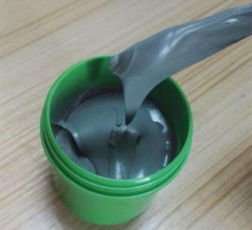
When soldering SMD components, solder can sometimes be used to make solder points shiny and strong. 7. Heat gunA heat gun is a tool that uses hot air blown from a cannon core to weld and disassemble components. The technological requirements for its use are relatively high. Heat guns can be used for everything from removing or installing small components to large integrated circuits. In different cases, there are special requirements for temperature and air volume of heat gun: if temperature is too low, components will be soldered, and if temperature is too high, components and circuit boards will be damaged. Excessive airflow can blow away small parts. For conventional overhead welding, you cannot use a heat gun, so I will not describe it in detail here. 8. Magnifying glassFor some SMD chips with extremely small and dense pins, after soldering is completed, it is necessary to check whether pins are soldered normally and there is no short circuit. The eyes are very laborious, so you can easily and reliably check condition with a magnifier solder each pin. 9. AlcoholWhen using rosin as a flux, it is easy to leave excess rosin on PCB. For beauty, you can use alcohol-based cotton pads to wipe off rosin residue from PCB
10. Other common tools needed for soldering patches include sponges, washboard water, stiff brushes, glue, etc. in addition to above.
Steps of manual soldering of patch components (soldering iron)
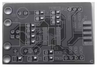
After learning about SMT soldering tools, soldering steps are now detailed. 1. Clean and fix PCB (PCB)Before soldering, PCB should be inspected to make sure it is clean (see Figure 2). Oily fingerprints and oxides on surface must be removed so as not to affect tinning.
When manually soldering a PCB, if conditions permit, a soldering station or similar can be used to facilitate soldering. As a rule, it is better to fix manually. It is worth noting that fingers should not touch contact pads on PCB to affect tinning.
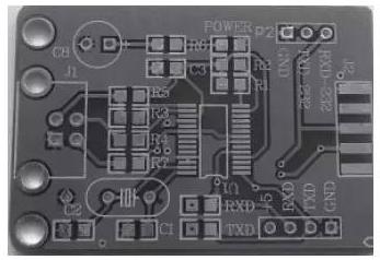 Rice. 2. Clean PCB
2. Attaching SMD ComponentsThe attachment of SMD components is very important. Depending on number of pins of SMD components, mounting methods can be roughly divided into two types: single-pin mounting method and multi-pin mounting method.
For SMD components with a small number of pins (usually 2-5), such as resistors, capacitors, diodes, triodes, etc., single-pin mounting method is usually used. That is, first tin contact pad on board (see Fig. 3).
 Rice. 3. For components with multiple pins, one should be tinned first
Then, holding component with tweezers in your left hand, place it in mounting position and touch PCB lightly, and with your right hand use soldering iron to melt solder next to tin pad to solder contact (see Figure 4).
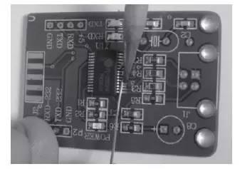
After soldering pad, component will not move, and at this time, you can release tweezers. For SMD chips with a large number of pins and a polyhedral distribution, it is difficult to fix chip with one pin, in this case, several pins are required, as a rule, you can use pin-to-pin fixing method (see Fig. 5).
That is, after soldering and fixing pin, solder and fix pin against pin to achieve purpose of fixing entire chip. It should be noted that for high pin count and dense SMD chips, accurate pin alignment is especially important and should be checked carefully, as soldering quality depends on this condition.
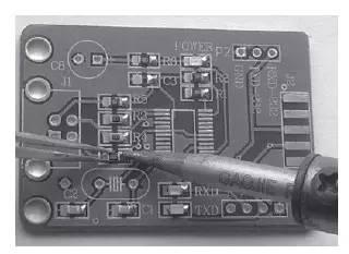
Figure 4 Fixed soldering components with multiple pins
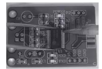 Figure 5. Soldering contacts or multiple contacts for components with a large number of contacts
It is worth emphasizing that pins of chip must be evaluated correctly. For example, sometimes we carefully fixed microcircuit and even soldered it, and when checking it, we found that pins did not match - we soldered not first pin as first! Regret too late! Therefore, these painstaking preliminary works should not be sloppy. 3. Solder rest of pinsAfter components are fixed, you need to solder rest of pins. For components with multiple pins, you can hold solder with your left hand and soldering iron with your right hand and alternate spot soldering.
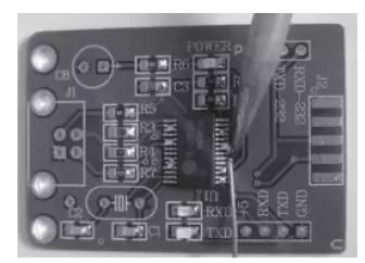
For chips with a large number and dense pins, in addition to spot welding, you can use resistance welding, that is, pour pins on one side with tin, and then melt solder with a soldering iron and wipe it off remaining contacts on side (see Fig. 6), melted solder can leak out, so sometimes board can be properly tilted to get rid of excess solder.
It is worth noting that, regardless of spot welding or resistance welding with tin, it is easy to close adjacent leads (see Fig. 7). Don't worry about it because you can get it. What you need to take care of is that all pins are well connected to pads and there is no false soldering.
 Rice. 6. Drag and drop SMT chips with a large number of pins
 Rice. 7. Don't worry about soldering shorted pins
4. Remove excess solder
In step 3, we mentioned shorted pins caused by soldering. Now let's talk about how to deal with excess solder.
Generally speaking, excess solder can be removed with tin-absorbing tape mentioned above. The method of using tin absorbent tape is very simple. Add an appropriate amount of flux (such as rosin) to solder absorbent tape and stick it to pad. Use a clean soldering iron tip to place it on tin. - absorbent tape After tin absorbent tape is heated to point where pad should be adsorbed After solder on pad has melted, slowly press and drag from one end of pad to other end and solder will be sucked into tape.
It should be noted that after tin absorption is completed, soldering iron tip and absorbent tin tape must be removed from pad at same time. pull solder absorbent tape. Instead, add flux to tin-absorbing strip or re-heat it with a soldering iron tip, then gently pull tin-absorbing strip so that it gently lifts off pad and prevents scalding of surrounding components.
If a special tin-absorbing tape is not commercially available, you can use thin copper wire in wire to make your own tin-absorbing tape (see fig. 8).
The homemade method is as follows: after removing outer sheath of wire, a thin copper wire inside is exposed. At this time, use a soldering iron to melt some rosin on copper wire.
The effect after removing excess solder is shown in fig. 9. In addition, if you are not satisfied with soldering results, you can reuse solder absorber to remove solder and re-solder components.
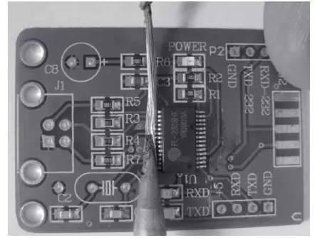 Figure 8. Gather excess solder on chip pins with homemade tin absorbent tape
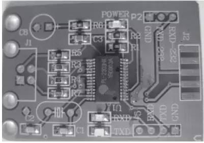
Fig. 9. Effect after removing excess solder from microcircuit pins
5. Clean soldering areaAfter soldering and removing excess solder, chip is almost soldered. However, due to use of rosin flux and tin-absorbing tape, some rosin remains around contacts of microcircuit on board (see Fig. 9). Although this does not affect operation and normal use of chip, it is not beautiful and may cause inconvenience during inspection.
Because we need to clean up these leftovers. A common cleaning method would be to use water to wash board. Alcohol is used for cleaning here. Cleaning tools can be cleaned with cotton swabs or toilet paper using tweezers (see Figure 10).
When cleaning and wiping, consider that alcohol should be moderate and its concentration should be relatively high in order to quickly dissolve residues such as rosin.
Secondly, erasing force must be well controlled, not too strong, so as not to scratch solder mask layer and damage chip pins.
The effect after cleaning is shown in Figure 11. At this time, you can use a soldering iron or a heat gun to properly heat place to be cleaned with alcohol so that remaining alcohol quickly evaporates. This completes soldering of microcircuit.
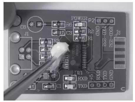 Rice. 10. Use alcohol to remove residual rosin during welding
Figure 11. Effect after cleaning welding site with alcohol
Steps for manual soldering of surface mount components
1. Preparation
1. Turn on heat gun, adjust air volume and temperature to appropriate position: feel air volume and duct temperature with your hands, observe whether air volume and duct temperature are unstable.
2. Note that inside of duct has a reddish tint. Avoid overheating inside blower. 3. Watch heat distribution with paper. Find center of temperature. 4. Use lowest temperature to purge resistor, and be aware of minimum temperature control setting that best purges resistor. 5. Adjust air volume knob so that steel ball indicating air volume is in middle position. 6. Adjust temperature controller so that temperature reading is around 380°C.
Note. If hair dryer is not used for a short time, turn it off if it is not used for more than 5 minutes.
Second, use a heat gun to detach flatpack IC:
1) Steps to remove flat package chip:1. Before removing components, check direction of chip and do not turn it upside down during assembly.
2. Check for heat-sensitive devices near IC, on front and back panels (such as liquid crystals, plastic components, BGA chips with sealant, etc.). If there are, cover their protective covers and like.
3. Add an appropriate rosin to IC pins that need to be removed to make PCB pads smooth after removing components, otherwise there will be burrs and it will be difficult to align them when rewelding.
4. Heat adjusted heat gun evenly over an area of about 20 square centimeters from component (the air nozzle is about 1 cm away from PCB, move faster in preheat position and temperature on PCB will not exceed 130-160°C)
1) Remove moisture from PCB to avoid "bubble" during rework.
2) Avoid stress warping and deformation between PCB pads caused by excessive temperature difference between top and bottom sides of PCB due to rapid heating of one side (top).
3) Reduce thermal shock of parts in welding zone due to heating above printed circuit board.
4) Avoid soldering and lifting adjacent chip due to uneven heating.
5) Heating printed circuit boards and components: nozzle of heat gun is at a distance of about 1 cm from IC, moving slowly and evenly along edge of IC and carefully clamping diagonallny part of IP with tweezers. .
6) If soldering point is heated to melting point, hand holding tweezers will immediately feel it. Be sure to wait until solder on IC lead is completely melted before going through "zero force". " Caution. Lift component vertically off board to avoid damaging PCB or IC, and to avoid short circuiting solder left on PCB. Heat control is key in rework and solder must be completely melted to avoid damaging pad when removing component.Be careful not to overheat board and warp board due to heat.(For example: if possible, you can choose 140°C-160°C for preheating and heating at bottom .The whole process of removing chip does not exceed 250 seconds)
7) After removing chip, check if solder points on PCB are short-circuited, if there is a short circuit, use a heat gun to heat it up again. circuit melts, use tweezers to lightly, solder naturally separates. Avoid using a soldering iron, as soldering iron will strip solder off board, and less solder on board, higher chance of false soldering. Filling tin pads with small pins is not easy.
2) Flat IC Installation Steps1. Check if pins of IC to be installed are flat. chip pins are wrong, use a scalpel to fix crooked parts.
2. Apply required amount of flux to solder pad. If it gets too hot, chip will float away. If there is too little flux, it will not work. And cover and protect surrounding heat-resistant components.
3. Place flat chip on pad in original direction and align pins of chip with pins on PCB. When aligned, eyes should look vertically down and leads on all sides should be aligned. Visually it is felt that length of pins is same on all sides, and pins are straight, not skewed. The phenomenon of rosin sticking when heated can be used for IC bonding.
4. Use a heat gun to preheat and heat IC. Please note that hair dryer cannot stop moving during whole process (if it stops moving, it will cause local temperature rise and damage), and watch IC during heating. If IC is found to be moving, use tweezers to gently adjust it without stopping heating. If there is no displacement phenomenon as long as solder under IC pins is melted, it should be detected for first time (if solder is melted, you will find that IC has a slight droop, rosin has a slight smoke, solder is shiny, etc., you can also use tweezers to gently lightly touch small components next tochip, if small components next to it move, this means that solder under contacts of microcircuit is also about to melt. ) and stop heating immediately. Because temperature set by heat gun is relatively high, temperature on IC board and PCB continues to rise. If temperature rise is not detected earlier, IC board or PCB will be damaged if temperature rise is too high. Therefore, heating time should not be too long.
5. After board has cooled, clean and dry solder points with thinner (or water to flush board). Check for soldering and short circuits.
6. If there is a false soldering situation, you can use a soldering iron to solder pins one by one, or remove IC with a heat gun and re-solder, if there is a short circuit, you can use a damp heat-resistant soldering sponge. After head has been wiped clean, moisten a little rosin and gently run it along contacts at short circuit to remove solder at short circuit. Or use tin-absorbing wires: With tweezers, pick out four tin-absorbing wires soaked in a little rosin, place them on a short circuit, and gently press with a soldering iron to tin-absorbing wires, solder in short circuit will melt and stick to tin-absorbing wires Eliminate short circuit.
Also: you can also use an electric soldering iron to solder chip. The distance between leads is larger, you can also add rosin, and use a soldering iron to roll all leads with tin balls for soldering.
3. Use a heat gun to desolder components that are afraid of heat
1) Remove components:Generally, such as cable clips, built-in connectors, connectors, SIM card holders, battery contacts, plugs and other plastic components are easily deformed by heat, if they are really damaged. If you want to remove it, you can remove it like a normal IC. If you want to remove it and keep it intact, you need to handle it with care. There is a rotating air heat gun with a uniform volume of air and heat that generally does not blow out plastic components.
If you are using a regular air gun, you can place PCB on edge of a table, use air gun to heat front and back of component from bottom to top, transferring heat up through PCB, and remove it after solder has melted; You can place an unwanted IC of same size on a heat-resistant component and then use an air gun to heat edge of IC. Once solder below has melted, plastic component can be removed.
2) Installing components: Position pads on printboard, dip pins of component in an appropriate amount of flux and place them close to pads so that they also receive some heat.
Use a hot air gun to heat circuit board. When solder on board is shiny, it means it has melted. Quickly carefully place components on pads. At this time, air gun can not stop moving and heating Use tweezers to adjust components in a short time Alignment, just evacuate air gun immediately.
This method is also suitable for installing power amplifiers and power ICs with large heat dissipation areas. Some devices can be easily soldered with a soldering iron (such as a SIM card holder), so do not use an air gun.
Fourthly, desoldering RC transistors and other small components
1) Component disassembly:1. Add an appropriate amount of rosin to components, gently pinch components with tweezers, and evenly move and heat small components with a hair dryer (same as desoldering a chip). The hand holding tweezers feels that solder has melted, and component can be removed.
2. Use a soldering iron on component. Add some solder in an appropriate amount and solder tin will coat solder joints on both sides of component. Place soldering iron tip flat on side of component so that newly added solder is in a state of melting and component can be removed. If component is large, you can add more tin to component's solder joint, pinch component with tweezers, and quickly heat two solder joints with a soldering iron until two solder joints are melted, and then they can be removed. .
2) Component installation:1. Add an appropriate amount of rosin to component, gently pinch component with tweezers, align component with solder joint, and move small component evenly heat with a hair dryer until solder under component melts, then release tweezers. (You can also set components in place and heat them up. After solder melts, touch components with tweezers to align them.)
2. Gently hold component with tweezers and press soldering iron on each pin of component to complete soldering. If there is less solder at soldering point, you can put a small tin bead on tip of soldering iron and add it to component pin.
5. Use a hair dryer to desolder screen:
1) Remove protective cover:Clamp PCB with a clamp, clamp protective cover with tweezers, heat entire protective cover with a hair dryer and lift it vertically upwards. after melting solder.
Because a high temperature is required to remove screen, other components on PCB will also be weakened. When removing screen, main board must not move,so as not to vibrate or move components on board. After removing shield, lift it vertically up to avoid hitting or displacing components in shield.
You can also lift up three sides of shield first, then fold it back and forth a few times after it cools down and break off last side to remove shield.
2) Install protective cover:Install protective cover on PCB, heat it with an air gun until solder is melted. You can also use a soldering iron to select a few spot welds on PCB.
Six, add virtual welding components:
1) Soldering with an air gunApply some rosin to part of circuit board to be soldered and heat it evenly with an air gun until solder on soldered part melts. You can also use tweezers to gently touch components suspected of false soldering in molten solder state to enhance soldering effect.
2) Soldering with an electric soldering ironUsed for soldering a small number of components. If it is IC soldering, you can add a small amount of rosin to IC pins, and use a smooth soldering iron tip to solder pins one by one after another.
Be sure to wipe off any remaining tin from soldering iron tip, otherwise it will short out contacts. If small components need to be added, such as welding resistors and triodes, simply dip tip of soldering iron in rosin and solder component leads. Sometimes a little solder can be added to contacts of a component to increase strength of weld.
Overview
Summarizing, soldering patch components is generally a patch-weld-clean process.
Fixing components is a prerequisite for quality soldering. Be patient and make sure that each pin is exactly aligned with corresponding pad.
When soldering multi-pin ICs, don't worry about short circuiting pins with solder. You can use a solder tape to soak up solder, or just use a soldering iron to remove excess solder using factors that flow after solder melts. Of course, mastering these skills takes practice.
Due to space constraints, only one type of multi-pin IC is soldered in this article. For many other types of multi-pin SMT ICs, pin density, mechanical strength, number, etc. are different. The corresponding welding method in this case is basically same, but details are slightly different.
So if you want to become an SMD soldering master, you need to practice more to improve your skills. If conditions allow, how skillfully can be used, if there are old printed circuit boards and old microshema.
Related
- Welding knowledge and skills that electronics professionals need to understand
- "English abbreviations" that equipment engineers need to know
- What skills should I pay attention to when designing a triode amplifier circuit? (Easy to understand)
- (Detailed long text) 7 ways to use diodes that engineers need to master
- An article to understand "advantages" and "cons" of solid capacitors
- Basic knowledge and introduction to structure of electric heating tube
- 7 things you need to know about high-speed linking and routing
- Do you understand all this knowledge of inductance?
- Why is analog electronics so hard to learn?
- Easy to understand! Explain PID
Hot Posts
 How to distinguish induction from leakage, we will teach you three tricks! Ordinary people can also learn super practical
- What is drowning in gold? Why Shen Jin?
- This is a metaphor for EMI/EMS/EMC that can be understood at a glance.
- How many types of pads have you seen in PCB design?
- Summary of Common PCB Repair Techniques
- What is three anti-paint? How to use it correctly?
- Knowing these rules, you will not get confused looking at circuit diagram.
- How to make anti-interference PCB design?
- Can diodes do this?