Location:Home Page > Archive Archive
Summary: Efficient Use of Decoupling Capacitors
2023-03-18【Archive】
The main points of effective use of decoupling capacitors can be roughly divided into following two types. In addition, a few more points should be noted.
01
Use multiple decoupling capacitors
One effective way to use decoupling capacitors is to use multiple capacitors instead of just one for decoupling. When using multiple capacitors, effect is different when using capacitors with same capacitance and when alternating capacitors with different capacitances.
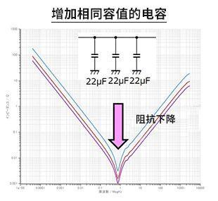
When using multiple capacitors of same value
The picture on right shows frequency response when using one 22uF capacitor (blue), adding one makes two (red), and adding one makes three (purple).
As shown in figure, when a capacitor of same capacitance is added, impedance changes downward over entire frequency range, i.e. impedance gets lower and lower.
This can be done by thinking about capacitance characteristics at resonance point when capacitors of same capacitance are connected in parallel, impedance of resonance point as a function of ESR (equivalent series resistance) and ESL (equivalent series inductance) after resonance point Perceptual properties of influencing understanding .
The capacitance values of capacitors connected in parallel are added, so capacitance of three capacitors is 66 uF, and impedance of capacitive region drops.
The resonance point impedance is equal to ESR of 3 capacitors connected in parallel, so  , assuming that ESR of these capacitors is same for all, ESR is reduced to 1/3, and impedance also drops.
ESL of inductive region after resonance point are also connected in parallel, so 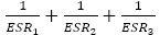 , assuming that ESL of all three capacitors are same, ESL is reduced to 1/3, and impedance also drops.
It can be seen that by using multiple capacitors with same capacitance, impedance can be reduced over entire frequency range, so noise can be further reduced.
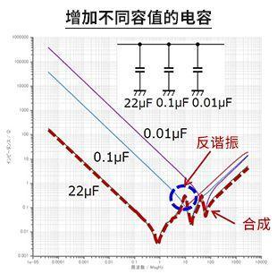
When using multiple capacitors of different capacities
These curves are frequency response after adding 0.1uF and 0.01uF capacitors in parallel based on 22uF capacitors.
By adding a capacitor with a smaller capacitance, you can reduce impedance of high frequency range. Compared to frequency response of a 22uF capacitor, 0.1uF and 0.01uF characteristics are synthesized characteristics (red dotted line).
It should be noted here that anti-resonance occurs at some frequency points, instead impedance increases and electromagnetic interference worsens. Antiresonance occurs at intersection of capacitive and inductive characteristics.
The capacitance of added capacitor usually needs to be selected according to target squelch frequency.
In addition, frequency response waveform diagram shown here is an ideal waveform diagram, and parasitic components caused by PCB layout and layout are not taken into account. In real measures to counter noise, it is necessary to take into account influence of parasitic components.
02
Decrease Capacitor ESL
The second key to efficient use of decoupling capacitors is to reduce ESL (ie equivalent series inductance) of capacitor. Although this is "reducing ESL", since ESL itself of one product cannot be changed, it means "even if capacitance is same, use a capacitor with a small ESL". By reducing ESL, high frequency performance can be improved and high frequency noise can be reduced more effectively.
Use smaller capacitors even if capacitance is same
For multilayer ceramic capacitors (MLCCs), sometimes several packages are prepared with same capacitance but different sizes. ESL depends on structure of pin site. Smaller capacitors generally have smaller leads and usually have a lower ESL.
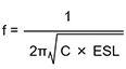
The figure on right shows an example of frequency response of capacitors of same capacitance but different sizes. As shown, smaller size 1005 has a higher resonant frequency and a lower impedance in frequency range after inductive region. This is same as introduced in "Frequency Responses of Capacitors". The resonant frequency of capacitors is based on following formula. It can be seen from formula that as long as capacitance is same, lower ESL, higher resonant frequency. In addition, impedance characteristics of inductive region depend on ESL, which has also been introduced.
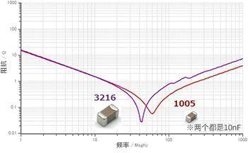
For noise reduction, when you want to reduce noise in higher frequency ranges, you can choose a small capacitor.
Use capacitors designed to reduce ESL
Among multilayer ceramic capacitors, some models use shapes and designs designed to reduce ESL.
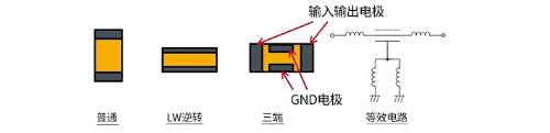
As shown in figure, electrodes of conventional capacitors are on short side, and reverse type LW electrodes are on opposite side, on long side. Since L (length) and W (width) are opposite, it is called "reverse type LW". This is type that lowers ESL by increasing width of electrode.
Three-terminal capacitors are capacitors with an optimized structure to improve frequency response of conventional capacitors (two terminals). A three-terminal capacitor should extend other end of one terminal (electrode) of a two-terminal capacitor as a through terminal, and use other terminal as a GND terminal. In figure above, input and output electrodes are equivalent to through-pins protruding from both ends, and left and right electrodes are, of course, conductive. Between input and output electrodes (through contacts) and GND electrode is a dielectric that acts as a capacitor.
Insert input and output electrodes into power line or signal line in series (connect one end of input and output electrodes to input terminal and other end to output terminal), and GND electrode to ground. Thus, since ESL of input and output electrodes are not included in ground terminal, impedance to ground becomes very low. In addition, ESL of input and output electrodes are inserted directly into noise path, which is useful for noise reduction (increase in insertion loss).
By arranging GND electrodes in pairs on long side, ESL can be suppressed, and then ESL can be halved by parallel connection.
With this structure, three-terminal capacitor not only has a very low ESL, but also can maintain a low ESR value, which can greatly improve high-frequency performance compared to a two-terminal capacitor of same capacitance. and size.
03
Additional Notes
①Higher Q ceramic capacitor
Capacitors have a Q characteristic. The figure below shows relationship between Q factor and frequency-impedance characteristics.
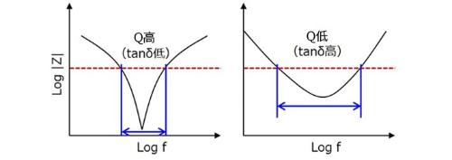
When Q value is high, impedance becomes very low over a certain narrow frequency band. When quality factor is low, although impedance will not drop much, it can be reduced over a wide frequency band. This feature can help you meet certain EMC standards. For example, when using a capacitor with a large change in capacitance, if Q factor is large, there may be persons who cannot eliminate noise at a given frequency. In this case, there is another way to suppress influence of fluctuations by using capacitors with a low quality factor.
②Heat Air Gasket PCB Graphics
For PCB templates such as hot air pads designed to improve heat dissipation, template's inductance component will increase. An increase in inductive component shifts resonant frequency towards lower frequencies, so in some cases desired noise reduction effect may not be obtained.
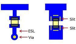
③Trial installation of a capacitor when discussing countermeasures
After trial production, you need to take measures against high frequency noise, and you can consider adding a small capacitor. At this time, as shown in figure below, if added capacitor is installed on top of main capacitor (example on left), an additional inductance component will be added vertically, so effect of adding a capacitor cannot be fully energized. In average example, impedance will be different from actual modified PCB layout, although theory of "place a small capacitor as close to noise source as possible" does not break. The best approach is to examine as close as possible to the actual changed configuration (correct example).
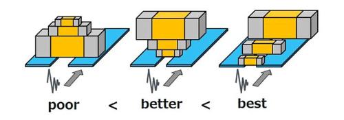
When discussing countermeasures, although noise test is OK, it may happen that when installed on a modified PCB, it will be NG, so it must be consciously set according to actual situation when discussing.
④Capacity Change Rate
When capacitance change rate of capacitor used for noise reduction is large, resonant frequency fluctuation will increase and target suppression bandwidth will change or fluctuate. It can sometimes be difficult to find ideal noise countermeasure. Special attention is required, especially when it is necessary to significantly suppress noise in a narrow frequency band. The table below shows relationship between rate of capacitance change and actual capacitance and resonant frequency. A close look at table shows that although this depends on conditions, in many cases this is not acceptable.
※ Calculated from L=1nH
⑤Temperature characteristics of capacitors
It is well known that performance of capacitors is affected by temperature. Currently, temperature characteristics of EMC tests are not standardized, but in some applications they must operate in conditions/environments with significant high or low temperatures, or be used in conditions/environments that cause large temperature changes.
In such cases, problems mentioned in "④ Capacity change rate" section are very likely to occur. Therefore, for noise suppression capacitors, it is necessary to use products with excellent temperature performance, which have characteristics of CH and C0G as much as possible. .
Related
- Summary: Efficient Use of Decoupling Capacitors
- Inventory of 27 functions of capacitors in circuits
- An interesting summary of PID algorithm full of haberdashery
- Summary of Common PCB Repair Techniques
- Summary of questions and answers on basics of analog circuits
- These 3 uses of capacitors cannot be understood
- Explain in detail classification of more than a dozen types of "recommended collection" capacitors
- An article to understand "advantages" and "cons" of solid capacitors
- The role of polar and non-polar capacitors in parallel connection
- Daniel's Summary: The details and experience of 30 PCB layouts are wonderful.
Hot Posts
 How to distinguish induction from leakage, we will teach you three tricks! Ordinary people can also learn super practical
- What is drowning in gold? Why Shen Jin?
- This is a metaphor for EMI/EMS/EMC that can be understood at a glance.
- How many types of pads have you seen in PCB design?
- Summary of Common PCB Repair Techniques
- What is three anti-paint? How to use it correctly?
- Knowing these rules, you will not get confused looking at circuit diagram.
- How to make anti-interference PCB design?
- Can diodes do this?