Location:Home Page > Archive Archive
About resistors, this is what you need to know
2023-05-09【Archive】
01 Basic Principles of Resistance
Resistors, along with inductors and capacitors, are three main passive devices in electronics; In terms of energy, resistors are energy-intensive components that convert electrical energy into thermal energy.
A few years ago, a fourth major passive device appeared, called a memristor, which reflects relationship between magnetic flux and electric charge. There is also a lot of information in XX library, if you are interested, you can take a look.
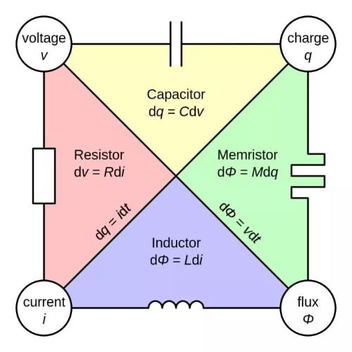
Image from Wikipedia Memristor
Usually, resistance is determined by Ohm's law, what current will be released when a constant voltage is applied to resistance, it can also be determined by Joule's law, when current flows through resistance, how much heat will be produced per unit time.
Real resistance equivalent model
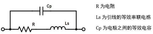
Similarly, actual resistance is not ideal, and there is a certain lead inductance and inter-electrode capacitance. With a high frequency of application, these factors cannot be ignored.
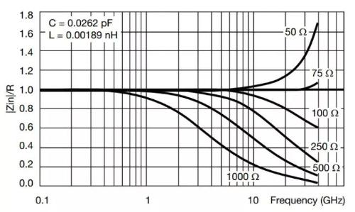
Frequency characteristics of a thin film resistor
The high-frequency performance of above resistor is very good: it can be seen that inter-electrode capacitance is only 0.03 pF, lead inductance is only 0.002 nH, and resistance of 75 ohms can reach 30 GHz. Most of chip resistors we generally use are thick film resistors, and their performance is far from that. The lead inductance is a few nH, and inter-electrode capacitance is also a few pF. Most of them can only be used in hundreds of MHz or a few GHz.
Table of standard resistances
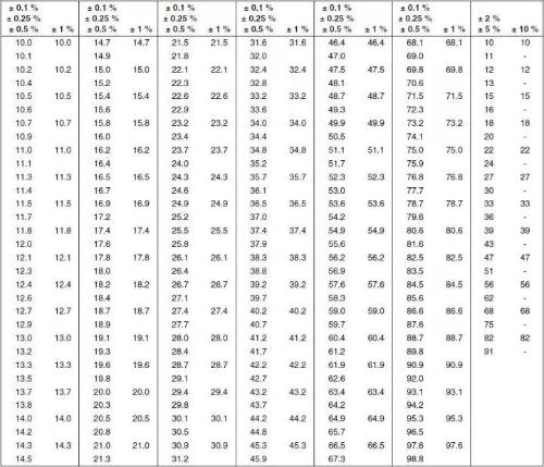
The image above is taken from Vishay document
Usually, resistance values are standard. The figure above shows standard resistance values of resistors with different accuracy (tolerances). Usually multiply by multiples of 10 or divide by multiples of 10 to get all resistance values.
How to remember above resistance table? It's actually very simple, pay attention to following three points:
Resistors with different accuracy correspond to series with different accuracy. Typically, 10% accuracy corresponds to E12 series, 2% and 5% to E24 series, 1% to E96 series and 0.1%, 0.25% and 0.5% to E192 series.
The number in series name indicates how many standard resistance values the series has, usually in multiples of 6. For example, E12 series has 12 different resistance values, and E192 series has 192 different resistance values.
The resistance value of each series is approximately a geometric progression, usual ratio is 10 to power of 10, and base is 10 ohms. For example, ordinary ratio of E12 series is 10 to 12th power, and ordinary ratio of E96 series is 10 to 96th power.
If you are interested, you can count according to above table, but if you do calculation, then not according to above rule. In addition, according to IEC regulations, 2% accuracy corresponds to 48 resistance values in E48 series. If you are interested, you can calculate values. In table above, Vishay may no longer produce this series.
Marking
We usually use 5% and 1% chip resistors most. As a rule, on packaging of resistors there is a marking above 0603 indicating value of resistance.
Series E24 (5%)
For resistance greater than 10 ohms, it is common to use 3 digits indicating resistance value, first two being base of resistance value, and last one being power multiplied by 10. For example, marking 100 corresponds to 10 ohms, not 100 ohms, and 472 corresponds to 4 .7 kOhm R is commonly used to represent a decimal point less than 10 ohms, such as 2R2 meaning 2.2 ohms.
Series E96 (1%)
Usually represented by two numbers plus a letter, two numbers represent resistance value of E96 series, and letters represent a multiplier of 10, where Y is -1, X is 0, A is 1, B is for 2, C is for 3, and so on Further. For example, 47C, counting 47 resistance values from table, is equal to 30.1, and C is a multiplication of 10 to third power, which is equal to 30.1 kΩ.
In addition, for axial lead package resistors, resistance label is a circle of colored rings, and specific value is shown in following figure:
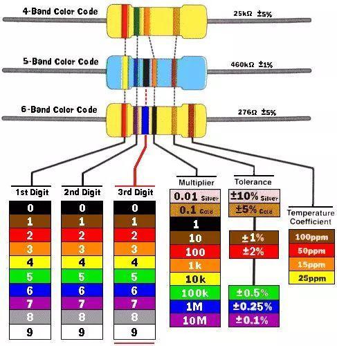
Resistance color ring code
From left to right, first two or three rings are numbers, and next rings are multipliers that are multiplied by previous numbers to get resistance value. The next ring represents tolerance of resistor and finally temperature coefficient of resistor.
02 Resistor technology and design
There are many types of resistors, which can be divided into two categories depending on ability to change value of resistance:
Fixed Resistors
Variable resistor
2.1 Fixed resistor
Fixed resistance, as name suggests, means that resistance value is fixed and cannot be changed. In most cases, resistors we use are of a fixed value. It can roughly be reclassified across different packages
2.1.1 Resistor with axial leads
Axial lead resistors are usually cylindrical, and two outer electrodes are axial wires at both ends of cylinder, which can be divided into several types based on materials and processes.
Wirewound resistor
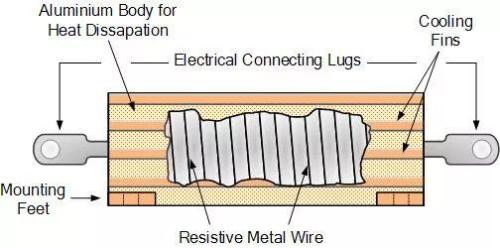
The resistance wire is a nickel-chromium alloy wire wound on an aluminum oxide ceramic substrate, and resistance is controlled one by one. Wirewound resistors can be made as precision resistors with a tolerance of 0.005% and a very low temperature coefficient. The disadvantage is that parasitic inductance of wirewound resistors is relatively large and cannot be used for high frequencies. The volume of wire resistor can be made very large, and then an external heat sink can be added, which can be used as a high power resistor.
Resistance to carbon composition

Carbon synthetic resistors are mainly sintered into cylindrical resistors using carbon powder and a binder. The concentration of charcoal powder determines resistance value. Tinned copper leads are added at both ends, which are finally packaged and formed. The carbon fusion resistor has a simple process and easy access to raw materials, so price is cheapest. However, performance of carbon synthetic resistors is not very good, tolerance is relatively large (that is, precision resistors cannot be manufactured), temperature performance is poor, and noise is usually relatively large. Carbon synthetic resistors have better pressure resistance. Since inside can be considered as a carbon rod, it basically won't break or burn.
Carbon film resistor
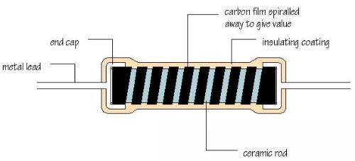
Carbon film resistance is mainly to form a layer of carbon mixture film on ceramic rod, such as directly coating layer, thickness of carbon film and concentration of carbon in it can control size of resistance; in order to more accurately control resistance, it can be used on carbon film. The spiral grooves are processed on top, and more spirals, more resistance, finally, metal leads are added and resin package is formed. The manufacturing process of carbon film resistors is more complicated, and precision resistors can be made, but due to carbon, temperature performance is still not very good.
Metal film resistor
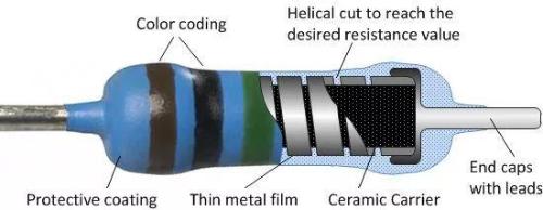
Similar to structure of carbon film resistors, metal film resistors mainly use vacuum deposition technology to form a nickel-chromium alloy plating layer on a ceramic rod, and then process spiral grooves on plating to precisely control resistance. It can be said that metal film resistors have best performance, high precision, and can be made in E192 series, and then have good temperature performance, low noise, and more stable.
Metal Oxide Film Resistor
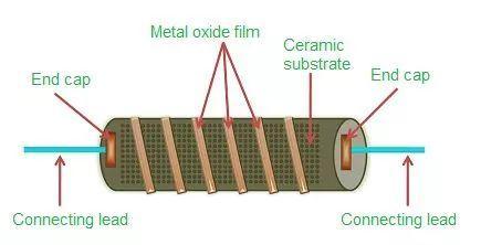
The image above shows a metal oxide film resistor
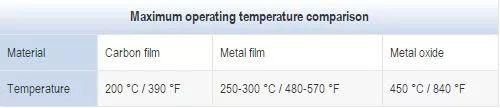
Similar to structure of a metal film resistor, a metal oxide film is basically a tin oxide film layer formed on a ceramic rod. To increase resistance, an antimony oxide film layer can be added to tin oxide film. and then on an oxide film. The diaphragm is machined with spiral grooves for precise resistance control. The biggest advantage of metal oxide film resistors is high temperature resistance.
The image above shows a metal oxide film resistor
2.1.2 Chip resistor
Metal foil resistor
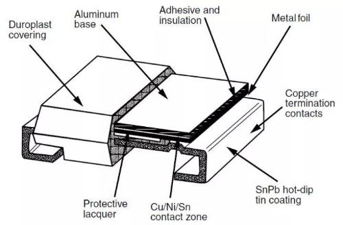
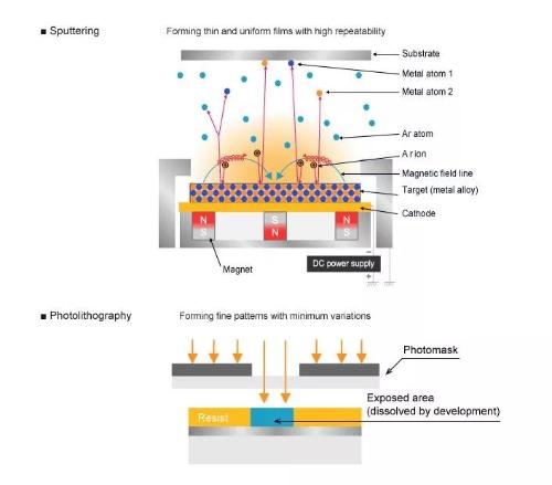
Metal foil resistors are made by vacuum melting to form a nickel-chromium alloy, and then rolled into metal foil, then metal foil is attached to aluminum oxide ceramic substrate, and then shape of metal foil is controlled. photolithography, thereby controlling resistance. Metal foil resistors are currently best resistors whose performance can be controlled.
Thick Film Resistor
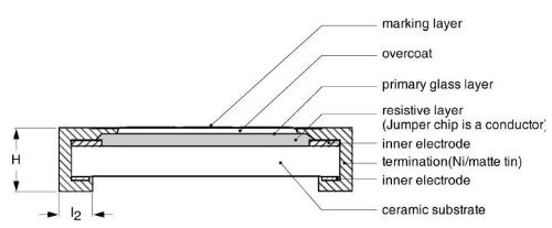
The screen printing method used in thick film resistors is to stick a layer of palladium silver electrode on a ceramic substrate and then print a layer of ruthenium dioxide between electrodes as a resistor. The resistive film of thick film resistors is usually relatively thick, around 100 microns. The specific technological process is shown in figure below.
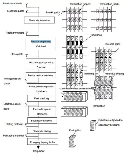
Thick film resistors are currently most widely used resistors. They are cheap and have a tolerance of 5% and 1%. Most products use 5% and 1% chip thick film resistors.
Thin Film Resistor
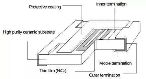
Thin film resistors are films of chromium and nickel formed by vacuum deposition on alumina ceramic substrates, typically only 0.1µm thick, which is only one thousandth of thickness of thick film resistors, and then etched into a specific shape using photolithography. The thin film process has been repeatedly mentioned in previous articles about capacitors and inductors. The photolithography process is very precise and can form complex shapes. Therefore, performance of thin film capacitors can be well controlled.
In image above, Panasonic chip resistors
2.2 Variable resistor
Variable resistor means that resistance value can be changed, and there are two types, one is a resistor whose resistance value can be manually adjusted, and other is a resistance value that can be changed according to other physical conditions.
2.2.1 Adjustable resistance
When I was in high school, I needed to use a sliding rheostat for experimentation. Move sliding rheostat and small bulb can be brighter or dimmer. The sliding rheostat is an adjustable resistor and principle is same.
Adjustable resistors are usually divided into three types:
Potentiometer
A potentiometer, or potentiometer, is a three-port device. The potentiometer is divided into two resistors by middle tap, and resistance value of two resistors can be changed through middle tap to change divided voltage.
Rheostat
The rheostat is actually a potentiometer. The only difference is that rheostat only needs two ports and is just a resistor that can adjust resistance precisely.
Trimmer
The trimmer is actually a potentiometer, but it doesn't need to be adjusted often. For example, it can be set when equipment leaves factory. Usually, special tools such as screwdrivers are required for adjustment.
2.2.2 Sensing resistor
Sensitive resistors are a type of sensing component. Most of these resistors are especially sensitive to certain physical conditions. As physical conditions change, resistance value changes accordingly. They can usually be used as sensors such as photosensitive resistors and moisture sensitive resistors. , magnetoresistors and so on. Thermistors and varistors should be used more in circuit design and are often used as protection devices.
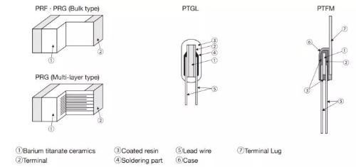
Thermistor
The image above is from Murata - PTC Application Guide
PTC is a positive temperature coefficient resistor. There are usually two types, one is ceramic material called CPTC, which is suitable for high voltage and high current cases, and other is resin material called PPTC, which is suitable for low voltage and small current cases.
Ceramic PTC, its resistive material is polycrystalline ceramic sintered from a mixture of barium carbonate, titanium dioxide and other materials. The temperature coefficient of PTC has a strong non-linearity. When temperature exceeds a certain threshold, resistance becomes very large, equivalent to an open circuit, so it can play role of short-circuit and over-current protection.
At same time, there is also a negative temperature coefficient resistor, i.e. NTC, which will not be presented in detail.
varistor
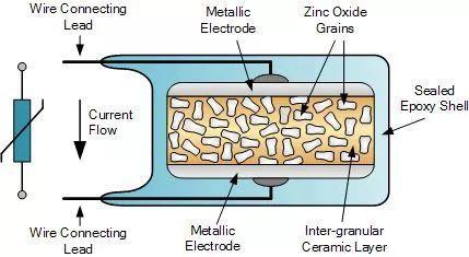
The image above is taken from varistor and metal oxide varistor tutorial
Varistors are usually metal oxide varistors, that is, metal oxide varistor (MOV), and their resistive materials are mixed with zinc oxide particles and ceramic particles and sintered together. The characteristic of MOV is that when voltage exceeds a certain threshold, resistance drops quickly and a large current can pass, so it can be used for surge protection and surge protection.
Multilayer varistors, namely MLVs, are made from zinc oxide ceramics using a process similar to MLCCs. The package of MLV is smaller, usually in shape of a chip, and its voltage rating and current capability are much smaller than those of MOV, which is suitable for low voltage DC applications.
03 Application and selection of resistors
Resistor manufacturers in China are mainly Yageo, Panasonic, Rohm, Vishay and Fenghua Hi-Tech.
3.1 Applying Resistance
In fact, no board is complete without resistors, and most commonly used components of any board are capacitors and resistors. Various pull-up and pull-up resistors, feedback resistors, etc. The level is limited, let me briefly describe it.
Thermal effects
According to Joule's law, when current flows through a resistor, it generates heat. There are also many uses for thermal resistance effect, such as electric blankets, electric fire barrels, and electric kettles.
For some outdoor electronic equipment, especially some SOCs integrated with high-performance processors, operating temperature requirements are very strict, and most of them can only meet commercial applications. Low, it is likely that machine cannot be turned on. Usually, a powerful resistor is added for preheating function, when temperature rises, device starts up and then turns off. Turn everything off, because power draw of device itself will also generate heat, which can maintain temperature.
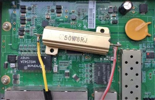
As an equipment engineer, I often have to go to environmental lab to troubleshoot problems. To reproduce high temperature problem, you need to go to environmental lab to set up a test environment. There are only a few main incubators and you have to make an appointment. The queue is too troublesome. Therefore, I made a very simple positioning artifact myself, which is to weld a DC socket to cement resistance, and then connect various power adapters to adjust temperature. Then put it on a certain chip for a few minutes, if there is no problem, replace it with another one, problem is repeated, problem is focused on a certain chip, and high temperature problem is in your own station.
Zero resistor
Resistors with zero resistance are also called jumper resistors. In circuit design, it is often used for debugging or compatibility purposes. For example, in preliminary design, to check operating current of each power supply of chip during debugging, it is usually necessary to divide power supply into several channels with zero-resistance resistors.
When using a zero resistance resistor, most common problem is how to calculate power consumption and how to determine if selected resistor meets requirements?
You currently need to get appropriate parameters from resistor specification. The figure below shows that zero-resistance resistor RC0402 has a resistance value of not more than 50 mΩ and a rated current of not more than 1A. This can be used to judge resistance. Whether it meets design requirements. Usually 0402 zero ohm resistor can meet current requirements below 1A.
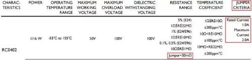
Original image taken from GENERAL PUPOSE CHIP RESISTORS - Yageo
Restriction
Sometimes a circuit requires a set of tens of milliamps of power, but its voltage is not used elsewhere in circuit. It is currently not practical to use only a DCDC or LDO set because current is too small. At this time, a Zener tube voltage regulator circuit can be used.
Unpacking
Voltage division such as ADC sampling circuit, DC output voltage feedback, level conversion, etc.
Resistance matching
For high-speed signals, PCB routing must consider transmission line model to ensure impedance matching and to prevent signal reflections from affecting signal integrity. Impedance matching must ensure that load impedance is equal to characteristic impedance of transmission line to eliminate reflections. The most commonly used and simplest is series end-of-source matching, that is, a resistor is connected in series at source end of signal, and sum of resistance and internal resistance of source is equal to impedance characteristic of transmission line, so even if end of load does not match, signal reflected back will be reflected source end signal and will not be reflected again.
In addition, there are various non-linear sensing resistors that can be used as sensors, protection circuits, etc.
3.2 Choosing Resistors
To put it simply, choice is to extract key parameters according to specifications of device and assess whether it meets requirements of application.
3.2.1 Fixed value resistor
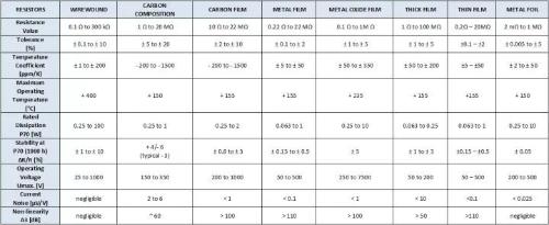
A comparison of main parameters of common types of resistors is shown in figure below, and largest batches should be thick film resistors and metal film resistors.
3.2.2 Thermistor
The main function of a PTC in a circuit is similar to that of a fuse, which is overcurrent protection. The difference is that fuse is disposable and PTC is resettable. In many cases, it is unacceptable to change fuse, which will affect customer experience. The PTC is also a safety device and usually requires UL1439 certification.
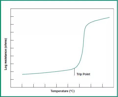
The figure above shows temperature-impedance characteristics of PTC. When an overcurrent occurs, PTC heats up and temperature rises rapidly, and impedance of PTC increases rapidly, forming an open circuit. Therefore, PTC is very suitable for short-term overcurrent.
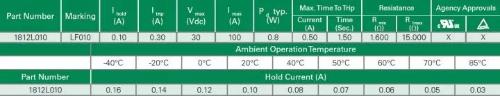
Keep current
When choosing a PTC, first thing to consider is rated operating current, which cannot exceed holding current of PTC. During this time, PTC can maintain a low impedance state. The PTC holding current will decrease as operating temperature rises, so operating temperature is an important factor to consider.
Motion current
The action current, that is, current at which PTC goes into a high impedance state and protects against an open circuit.
Rated voltage
This is maximum voltage that PTC can withstand. If rated voltage exceeds rated voltage, PTC may fail and cause a short circuit, resulting in burnout. Therefore, when designing, it should be taken into account that operating voltage of PTC cannot exceed its rated voltage under various circumstances.
When PTC is protected against open circuit, it will withstand entire power supply voltage. If PTC is selected, rated voltage must be greater than power supply voltage. Usually derating to 80% is considered, i.e. 12V supply voltage, and a PTC with a withstand voltage of 15V or more should be selected.
Surge protection must be provided on power input port. At this time, maximum surge current multiplied by resistance of PTC should be taken into account, that is, surge voltage that PTC can withstand cannot exceed rated voltage of PTC.
Rated currentThis is maximum short circuit current that PTC can withstand at rated voltage. If short circuit current exceeds rated current, PTC will be damaged.
DC resistance
The presence of PTC DC resistance will cause some DC voltage drop in PTC. When designing, pay attention to supply voltage after voltage drop to meet requirements.
Compared to fuses, PTC's voltage rating and current rating are much smaller, and PTC's DC resistance is typically about twice that of fuses. When PTC is protected, it is effectively in a high resistance state, so there will be milliamp leakage current, while fuse is a fuse that cuts off current path, and there is basically no leakage current.
3.2.3 Varistor
Varistors are similar in characteristics to zener diodes and TVS. They are all clamping devices and are mainly used to protect circuits from transient surges such as power surges.
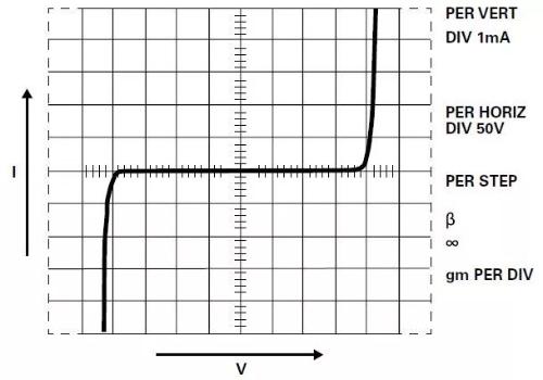
Ideal MOV volt-ampere characteristics
When selecting protective devices, two aspects are mainly considered: firstly, protective device cannot work or be damaged under normal operating conditions, and secondly, it must be able to protect circuit under abnormal conditions within design range, that is, ability to protect.
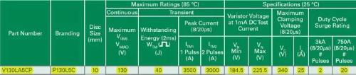
Rated operating voltage
The rated operating voltage can be thought of as maximum continuous operating voltage for MOV to maintain a high impedance condition. According to application, MOV can be divided into AC and DC, and characteristics of devices used in these two cases are different. MOVs used in DC applications generally cannot be used in AC applications.
MOV rated operating voltage, AC rated voltage is considered in case of AC, that is, Vrms or Vm(ac), device in above figure can normally operate on AC mains with 130 V rms. If this voltage is exceeded, The MOV may trip or fail, causing circuit to fail.
It is mainly used for transient high voltage protection, and permanent overvoltage may damage MOV.
Clamping voltage
MOV is a clamping device. When encountering a transient high voltage, impedance will drop. With a large current, transient high voltage will be suppressed, but will not drop to zero, but will maintain a relatively high voltage. , usually rated work is 2-3 times voltage. When choosing MOV, please note that clamping voltage cannot exceed maximum withstand voltage of protected device. If it exceeds, multi-level protection is required. For example, add a powerful decoupling resistor to rear stage, and add TVS residual stress.
Maximum surge current
Lightning strikes or switching of an inductive load, etc., can generate a large surge current. In addition to clamping high voltage, MOV must also drain surge current.
The ability of an MOV to withstand a surge current mainly depends on amount of power that MOV can withstand for a certain period of time. If energy is too high, MOV will overheat and burn out. The amount of energy is related to waveform and number of surges. Typically, surge capability of a device is tested according to wave energy of 8/20 µs. The MOV in figure above has one 3500 A 8/20 µs surge, two consecutive 3000 A 8/20 µs surges, and 20 consecutive 750 A 8/20 µs surges.
In addition, parasitic capacitance of MOV is relatively large, so it cannot be used on high-speed signal lines. MOV response time is faster than TVS and may not work for some fast pulses such as ESD. These are also factors that we need to take into account.
Related
- About resistors, this is what you need to know
- What you need to know about semiconductor chips
- 7 things you need to know about high-speed linking and routing
- What do you know about fuse classification?
- Do you know all this little knowledge about inverters?
- Resistors Secret - Resistor Parameters You Should Know
- What is difference between 0 ohm resistors, inductors and magnetic balls? After reading this I finally got the answer
- How to choose a suitable power chip, do you know this?
- What is difference between 0 ohm resistors, inductors and magnetic balls for single point grounding?
- Do you know everything about communication, decoupling and capacitance?
Hot Posts
 How to distinguish induction from leakage, we will teach you three tricks! Ordinary people can also learn super practical
- What is drowning in gold? Why Shen Jin?
- This is a metaphor for EMI/EMS/EMC that can be understood at a glance.
- How many types of pads have you seen in PCB design?
- Summary of Common PCB Repair Techniques
- What is three anti-paint? How to use it correctly?
- Knowing these rules, you will not get confused looking at circuit diagram.
- How to make anti-interference PCB design?
- Can diodes do this?