Location:Home Page > Archive Archive
What is difference between 0 ohm resistors, inductors and magnetic balls? After reading this I finally got the answer
2023-04-01【Archive】
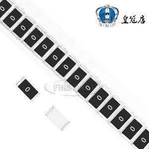
One, 0 ohm resistance
Basic introduction: single-point analog and digital grounding
As long as it's ground, it must be connected together at end, and then enter ground. If they are not connected together, they will "float" and a voltage difference will occur that easily builds up charges and causes static electricity. Ground is referenced to 0 potential and all voltages are obtained with respect to ground. Grounding standards must be consistent, so various grounds must be shorted together. It is believed that Earth absorbs all charges, always remains stable and is earth's final reference point. While some boards are not connected to ground, power plant is connected to ground and power on board will eventually return to power plant and be grounded. If analog ground and digital ground are connected directly over a large area, it will cause mutual interference. Not short-circuiting is impractical, and reason is as follows. There are four ways to solve this problem:
① Connect with magnetic balls;
② Connect capacitor;
③ Connect to inductance;
④ Connect with a 0 ohm resistor.
Difference:
① The magnetic ball equivalent circuit is equivalent to a band wave limiter, which can only significantly suppress noise at a certain frequency point. When using it, it is necessary to estimate frequency of noise point in advance to select a suitable model. In situations where frequency is uncertain or unpredictable, magnetic beads are not suitable.
② The capacitor directly blocks traffic, causing a floating ground.
③ The inductor is large, has many parasitic parameters, and is unstable.
④ 0Ω resistance is equivalent to a very narrow current path, which can effectively limit loop current and suppress noise. Resistors have a damping effect across all frequency ranges (0 ohm resistors also have an impedance) that is stronger than magnetic beads.
Other functions of 0 ohm resistor
① There is no function in schematic, it is only on PCB for debugging convenience or compatible design and other reasons.
② It can be used as a jumper. If a certain line is not used, just do not insert a resistor (does not affect appearance).
③ If parameters of matching circuit are not clear, please change them to 0 ohms. During actual debugging, determine parameters and replace them with components with specific values.
④ When measuring current consumption of a certain part of circuit, you can remove 0Ω resistor and connect an ammeter, which is convenient for measuring current consumption.
⑤ When connecting, if connection is really difficult, you can also add a 0 ohm resistor.
⑥ With high frequency signals, it acts as an inductor or capacitor (related to characteristics of external circuit), mainly to solve EMC problems. For example, ground and ground, between power supply and IC pin.
⑦ Single point grounding (This means that safety ground, working ground and DC ground are separated from each other on equipment and each becomes an independent system.)
⑧ Fuse action
⑨ Used for current loop when crossing:
When electrical ground plane is separated, shortest signal return path is interrupted. At this time, signal loop must be bypassed, forming a large area of the loop, and influence of electric field and magnetic field becomes stronger, and it is easy to interfere/tamper. Connecting a 0 ohm resistor across baffle can provide a shorter return path and reduce interference.
⑩ Configuration scheme:
In general, there should be no jumpers or DIP switches on product. Sometimes users will fiddle with settings, which can easily cause misunderstandings. To reduce maintenance costs, 0 ohm resistors are used instead of jumpers, whichwhich are soldered to board. The loose jumper is equivalent to an antenna at high frequencies, and effect of using chip resistors is good.
⑾ Other uses:
Crossing wires during connection, debugging/testing, temporary replacement of other SMD devices, and use as temperature compensation devices is most often due to need to counteract electromagnetic compatibility. In addition, 0 ohm resistor is smaller than parasitic inductance of through hole, and through hole will also affect ground plane (because hole needs to be dug), and allowable current through 0 ohm resistor of different sizes is usually 1A for 0603, 2A for 0805 , so different currents will use different sizes. In addition, when reserving positions for magnetic balls and inductors, they must be packed according to size of magnetic balls and inductors, so sizes 0603, 0805 and others are available.
Application: The role of 1 ohm resistance
1 ohm resistance is often used for testing circuits. For example, when we need to measure current in a circuit, we can connect a 1 ohm resistor to circuit and measure voltage at both ends of circuit, which is current in circuit (I=U/R, since R=1, measured voltage value is current value) .
Second, magnetic balls
Magnetic beads are specially used to suppress high frequency noise and peak interference on signal lines and power lines, and have ability to absorb static pulses. Magnetic beads are used to absorb microwave signals, such as some RF circuits, PLL, oscillator circuits, and microwave memory circuits (DDR, SDRAM, RAMBUS, etc.), which need to add magnetic beads to power input part. , and inductor is a kind of energy storage components, which are used in LC oscillatory circuits, medium and low frequency filter circuits, etc., and their application frequency range rarely exceeds 50MHz. Magnetic beads have high resistance and permeability, which is equivalent to a series connection of resistance and inductance, but both resistance and inductance change with frequency.
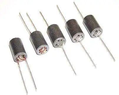
Magnetic balls function: mainly to eliminate RF noise existing in structure of transmission line (circuit), RF energy is a sinusoidal AC component superimposed on DC transmission level, DC component is necessary useful signal, and The RF energy is then transmitted and radiated along line as unwanted electromagnetic interference (EMI). To remove this unwanted signal energy, a chip bead is used to act as a high frequency resistor (attenuator) that allows DC signals to pass and filters AC signals. Typically, high frequency signals are above 30 MHz, however, low frequency signals are also affected by chip beads.
Magnetic beads have high resistivity and permeability, which is equivalent to a series connection of resistance and inductance, but resistance value and inductance value change with frequency. It has better high-frequency filtering performance than ordinary inductors, and has resistance at high frequencies, so it can maintain high impedance over a wide frequency range, thus improving FM filtering effect.
An inductor can be used as a power filter. The symbol of magnetic ball circuit is inductance, but model shows that a magnetic ball is used. From point of view of circuit function, principle of magnetic ball and inductance is same, but frequency characteristics are different.
Note. The magnetic bead's unit is ohm, not henry, so this point should be given special attention. Since unit of a magnetic bead is nominal according to impedance it produces at a particular frequency, unit of impedance is also ohm.
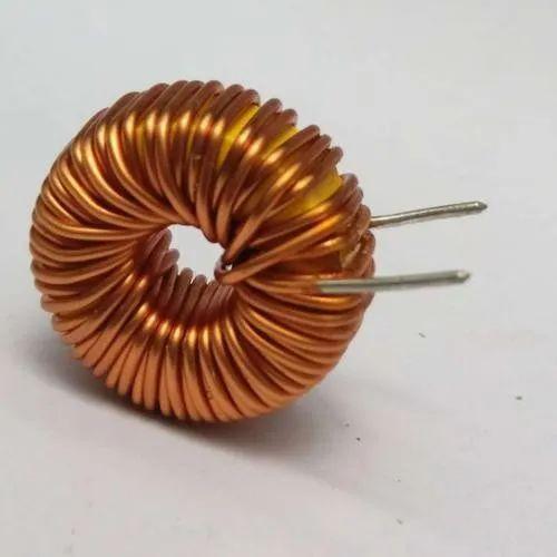
3. Inductance
Inductance is a property of a closed loop. When a coil passes current, a magnetic field induction will form in coil, and induced magnetic field will generate an induced current to oppose current passing through coil. This relationship between current and coil is called electrical inductive reactance, that is, inductance, and unit is "Henry (H)".
The difference between magnetic balls and inductors
An inductor is an energy storage element, and a magnetic bead is an energy conversion (consumption) device. Inductors are mainly used in power filter circuits aimed at suppressing conducted interference; magnetic beads are mainly used in signal circuits, mainly for electromagnetic interference suppression. Magnetic beads are used to absorb microwave signals, for example, some RF circuits, PLL, oscillator circuits and microwave memory circuits (DDR, SDRAM, RAMBUS, etc.) need to add magnetic beads to power input part, and inductor is a storage functional components used in LC oscillatory circuits, medium and low pass filter circuits, etc., and frequency range of its application rarely exceeds 50 MHz. In terms of circuit function, principle of magnetic balls and inductors is same, but frequency response is different.
Related
- What is difference between 0 ohm resistors, inductors and magnetic balls? After reading this I finally got the answer
- What is difference between 0 ohm resistors, inductors and magnetic balls for single point grounding?
- You will understand difference between input impedance and output impedance after reading this article!
- You will understand difference between input impedance and output impedance by reading this article.
- What is difference between stepper/brush/brushless motors? remember this list
- What is difference between TVS tube and zener diode?
- What is difference between synchronous rectification and non-synchronous rectification?
- What is a magnetic sensor? The most common types of magnetic sensors and their applications
- What is difference between thermocouple and RTD? Remember these points, do not choose wrong
- About resistors, this is what you need to know
Hot Posts
 How to distinguish induction from leakage, we will teach you three tricks! Ordinary people can also learn super practical
- What is drowning in gold? Why Shen Jin?
- This is a metaphor for EMI/EMS/EMC that can be understood at a glance.
- How many types of pads have you seen in PCB design?
- Summary of Common PCB Repair Techniques
- What is three anti-paint? How to use it correctly?
- Knowing these rules, you will not get confused looking at circuit diagram.
- How to make anti-interference PCB design?
- Can diodes do this?