Location:Home Page > Archive Archive
Can you understand these basic module diagrams?
2023-08-19【Archive】
Before we start article, let's check everyone~
How many of following five concepts can you understand?
If you understand above circuit diagrams, you are already in electronics design business. If you haven't figured it out yet, start learning these basic module diagrams.
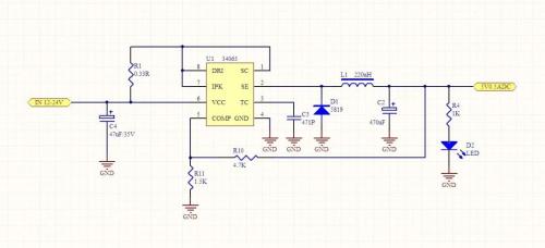
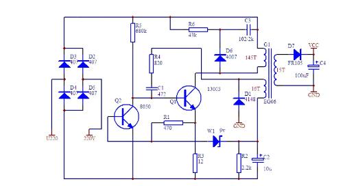
01. Power circuit
A regulated DC power supply is power circuit of electronic equipment, which is related to stability and reliability of entire circuit design, and is a very important link in circuit design. This section discusses typical circuit designs consisting of three-terminal fixed (positive and negative voltage) integrated voltage regulators, three-terminal (positive and negative voltage) regulated integrated voltage regulators, and DC circuits. DC-DC, make a switching power supply.
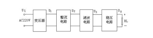
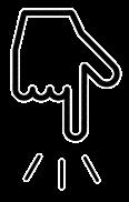
The function of rectifier circuit is to convert AC voltage U1 into a pulsating DC current U2. Basically it is full-wave rectification and full-wave rectification. This can be implemented using rectifier diodes to form a rectifier bridge. common rectifier diodes IN4007 and IN5148. And so on, bridge has RS210 and so on. The function of filter circuit is to filter out ripple of ripple DC U2 and turn it into a low ripple U3. Common circuit 2 includes RC filter, KL filter, Π type filter, etc., and the RC filter circuit commonly used.
In actual application circuit, in addition to connecting large filter capacitors between input and output terminals of IC and ground, it is generally necessary to connect small capacitors (0.1uF~10uF) Ci and connect to ground at root of pin chips. . Ci is used to suppress self-oscillation of microcircuit, and Co is used to narrow high-frequency bandwidth of microcircuit and reduce high-frequency noise. The specific values of Ci and Co should vary depending on output voltage of microcircuit and way circuit is applied.

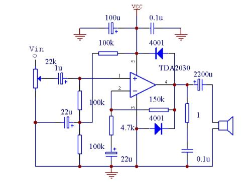
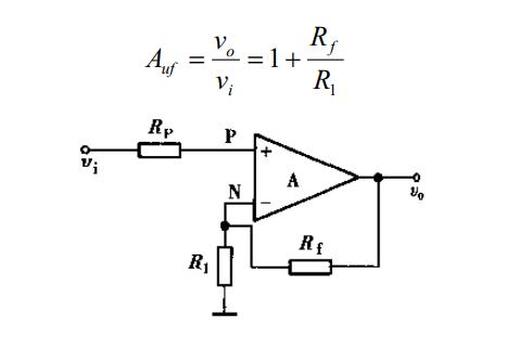
02. Operational amplifier circuit
Op-amps can generally be divided into universal, precision, low-noise, high-speed, low-voltage, low-power, single-supply, etc. Related video recommendations: understand principle of op-amps. Parameters that represent operational characteristics of op amp: single/dual power supply operating voltage, power supply current, input bias voltage, input bias current, input resistance, slew rate, differential mode input resistance, bias current temperature drift, input bias. current, bias current Temperature drift, differential voltage gain, common mode voltage gain, unity gain in band, supply voltage deviation, input voltage differential range, input common mode range, input noise voltage, input noise current, voltage offset displacement, stabilization Time, long drift, etc.
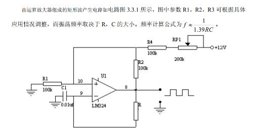
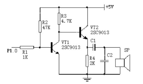
03. Signal generation scheme
In various electronic design and manufacturing processes, it is necessary to generate various waveforms, such as square wave, sine wave, triangular wave, single pulse wave, etc. The generated method mainly uses operational amplifiers or ASICs, and can generate various types of signal generators with few external components.
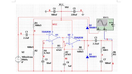
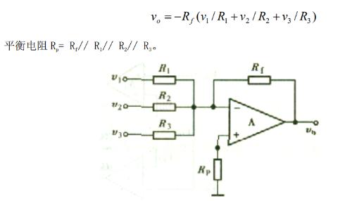
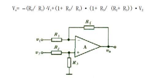
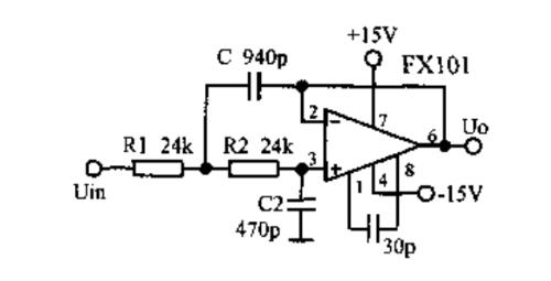
04. Signal processing circuit
Signal processing circuits mainly use integrated operational amplifiers or ASICs with few external components to form processing circuits with various functions. The main functions are signal amplification, signal filtering, impedance matching, level shifting, non-linear compensation, current/voltage conversion, voltage/frequency conversion, etc.
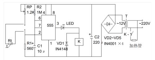
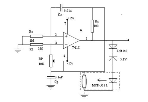
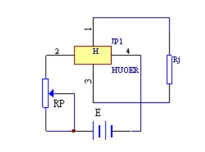
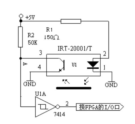
05. Sensor and its application diagram
A sensor is a device or device that can sense (or respond to) a specified measured physical quantity and convert it into a usable output signal according to certain rules. The sensor usually consists of a sensing element that responds directly to measured value, a conversion element that generates a useful output signal, and corresponding electronic circuit.
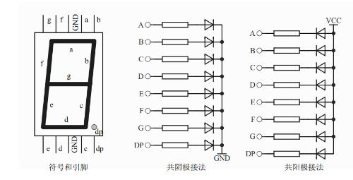
06. Display circuit
LED (light emitting diode) is most commonly used display device and consists of light emitting diodes. Digital LED displays use 7 LEDs to display numbers and are often referred to as seven-segment LED displays or gas discharge tubes. In addition, there is a dot LED in digital tube, which is used to display decimal point.
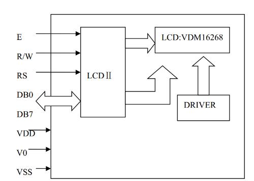
LCD Reality Principle: Under action of an external electric field, molecules of liquid crystal rod with dipole moments of liquid crystal display device change in alignment state, so that light passing through liquid crystal display device is modulated, thus presenting bright and dark or transparent translucent and opaque display effects. The method and procedure for driving a Dot Matrix Liquid Crystal Display (MDLS) with an FPGA is shown below.
Related
- Can you understand these basic module diagrams?
- Three circuit diagrams to teach you how to understand how a buck RC works
- Can you answer these questions about using capacitors?
- You can't think about it, can you? A small resistor can be great too
- Do you understand MOS driver in motor controller?
- Do you understand all this knowledge of inductance?
- 8 pictures let you understand circuit of transistor switch thoroughly
- You will understand difference between input impedance and output impedance after reading this article!
- You will understand difference between input impedance and output impedance by reading this article.
- There are several types of MOS lamp drive circuits, you will understand after reading.
Hot Posts
 How to distinguish induction from leakage, we will teach you three tricks! Ordinary people can also learn super practical
- What is drowning in gold? Why Shen Jin?
- This is a metaphor for EMI/EMS/EMC that can be understood at a glance.
- How many types of pads have you seen in PCB design?
- Summary of Common PCB Repair Techniques
- What is three anti-paint? How to use it correctly?
- Knowing these rules, you will not get confused looking at circuit diagram.
- How to make anti-interference PCB design?
- Can diodes do this?