Location:Home Page > Archive Archive
Buck Output Capacity Calculation
2023-08-22【Archive】
The buck topology is widely used in electronic products, but many engineers are not very clear about choice of capacitors. The following describes how to select a capacitor when buck converter is in critical mode and in continuous mode.
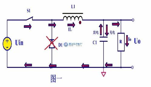
Figure 1 below shows current flowing when switch is turned on. When switch is turned on, capacitor current is charged and discharged, but charging must be balanced.
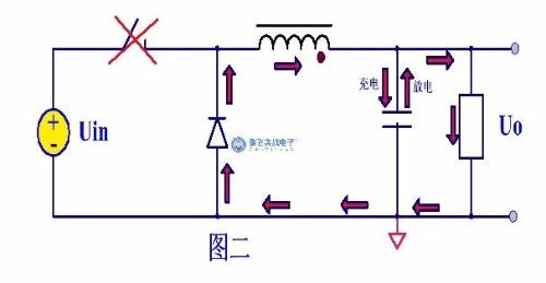
In fig. 2 shows current flow when switch is off. Capacitors also undergo charging and discharging processes during shutdown.
From above figure, when step-down circuit is in a steady state, inductor current is in a critical state. When switch S1 is closed at time t0, current in inductor L1 starts to rise from 0. In this time, output voltage passes through capacitor C1 The discharge to maintain voltage is basically balanced, so voltage of output capacitor drops. As time goes by time t1, when inductor current rises to output current IO, it can be considered that capacitor does not charge or discharge, but inductor current continues after time t1, at this time, when IL>Io increases, capacitor starts charging. The capacitor voltage starts to rise and at time t2 switch lamp turns off, inductor current reaches its maximum ILmax>Io, output capacitor continues to charge, voltage rises, and inductor current starts to fall after time t2 to t3, and when IL>Io, output The capacitor is still charging up to time t3, inductor current IL=Io fully provides load current, there is no additional current to charge capacitor, voltage of capacitor without charging reaches its maximum value, after time t3 inductor current IL
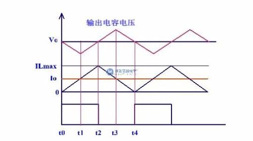
From figure below, charging time of electrolytic capacitor is t1-t3, when current of inductor is IL>Io, voltage across capacitor rises to △V, time t1-t2 is 1/2 turn. - on time, t2-t3 The time is 1/2 of off time, the time period t1-t3 is  , that is, charge time of capacitor is half a period.
The discharge time is half a cycle and average charging current is 
During whole charging process, charging voltage of capacitor is charged from minimum voltage to maximum voltage, and voltage difference from minimum voltage to maximum voltage is △V, △V=Vomax-Vomin, where △V is caused by charging and discharging of capacitor Voltage ripple, average current of inductor in BUCK circuit is equal to output current Io, so ILmax=2 Io in critical mode BUCK
Thus, you can get average charging current of capacitor Iav=Io/2
According to Q=C V=I t 
The critical current is average charging current 
The critical mode time is charging time of capacitor. 
△V is required ripple voltage, typically 1% or 2% of output voltage
Calculated by formula 
In critical mode △I=2 Io 
If it is in continuous mode, △I=r×Io
r takes values from 0.2 to 0.4. 
Related
- Buck Output Capacity Calculation
- Understanding input impedance and output impedance
- How did BUCK scheme come about? Application: 3 kinds of evolutionary chains
- Principal analysis of BUCK / BOOST circuit, a summary is also in place
- Three circuit diagrams to teach you how to understand how a buck RC works
- Four ways to reduce the output "ripple and noise" of a switching power supply
- You will understand difference between input impedance and output impedance after reading this article!
- You will understand difference between input impedance and output impedance by reading this article.
Hot Posts
 How to distinguish induction from leakage, we will teach you three tricks! Ordinary people can also learn super practical
- What is drowning in gold? Why Shen Jin?
- This is a metaphor for EMI/EMS/EMC that can be understood at a glance.
- How many types of pads have you seen in PCB design?
- Summary of Common PCB Repair Techniques
- What is three anti-paint? How to use it correctly?
- Knowing these rules, you will not get confused looking at circuit diagram.
- How to make anti-interference PCB design?
- Can diodes do this?