Location:Home Page > Archive Archive
Understanding input impedance and output impedance
2023-03-18【Archive】
Input impedance
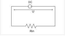
Input resistance (input resistance) refers to equivalent circuit input resistance. Add a voltage source U to input terminal, measure current I at input terminal, then input resistance Rin will be U/I. You can think of an input as two ends of a resistor, and that resistor's resistance is input impedance.
In case of same input voltage, if input impedance is very low, a large current must flow, which will test current output capability of previous stage; and if input impedance is high, then only a small current, which reduces current load on output power of previous stage. Therefore, try to increase input resistance in circuitry.
Input resistance is no different from a conventional reactive element, it reflects amount of resistance to current. For a voltage controlled circuit, greater input impedance, less stress on voltage source, so it is easier to control and does not affect signal source; while for a current driven circuit, lower input resistance, lower load on current source. Therefore, we can think of it this way: if it is driven by a voltage source, greater input impedance, better; if it is driven by a current source, lower impedance, better (Note: Only suitable for low-frequency circuits. The circuit should also consider problem of impedance matching.) In addition, if you need to get maximum output power, you should also consider problem of impedance matching.
Voltage source controlled circuit
The so-called voltage source drive can be understood as a constant voltage battery that has no internal resistance and is always full of energy as an energy source to power load.
A voltage source U, similar to a power source, is applied to both ends of load to generate current I, then load impedance Rin is equal to U/I. The power consumed by load is P=UI=U/Rin. It can be seen from formula that Rin here always plays a role in reducing current I. The larger Rin, less energy consumed by load, here load impedance is input of load impedance.
Circuit driven by a current source
In contrast to a voltage source controlled circuit, a current source drive can be understood as a source of DC power I that supplies power to a load.
Ohm's law shows that generated voltage is equal to U=I*Rin, and power consumed by load is equal to P=U*I=I*I*Rin. From formula, you can see that input load resistance Rin plays a role here in increasing power Function, circuit is controlled by a constant current source, larger resistance, higher voltage on load and greater power consumption.
Output impedance
The output impedance (output impedance) includes internal resistance of equivalent voltage source (Thevenin equivalent circuit) or equivalent current source (Norton equivalent circuit) at independent power supply output port. Its value is equal to input impedance seen from output port when independent power supply is set to zero.
Regardless of signal source, amplifier or power supply, there is a problem with output impedance. The output impedance is internal resistance of signal source. Initially, for an ideal voltage source (including a power source), internal resistance must be 0, or impedance of an ideal current source must be infinite. The output impedance requires special attention when designing a circuit.
Actually, a voltage source cannot do this. An ideal voltage source is often used in series with a resistor r to be equivalent to a real voltage source. This resistance r in series with an ideal voltage source is internal resistance of signal source/output amplifier/power supply. When this voltage source energizes load, a current I will flow through load and a voltage drop I×r will be generated across this resistance. This will cause output voltage of power supply to drop, limiting maximum output power. Similarly, for an ideal current source, output resistance should be infinite, but this is not possible in a real circuit.
The output impedance refers to equivalent circuit resistance when viewedb on circuit load from output port of circuit. In fact, it is mainly for power source or output circuit. This is impedance measured by power source. at exit. , commonly known as internal resistance.
Voltage source controlled circuit
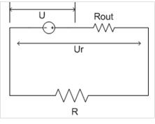
When a voltage source is applied to a load, in addition to consuming power at end of load, it also consumes power itself. This is because when a voltage source outputs energy, there is internal resistance that prevents energy from escaping. , such as internal resistance of battery. For example, constant voltage source U, output impedance Rout, load terminal voltage Ur, load R, current I=U/(Rout+R), load terminal voltage Ur=I*R=U *R/(Rout+R) , power generated by load is P=Ur*I=U2*R/(Rout+R)2. From this formula, it can be seen that lower output impedance, greater ability to drive load.
Circuit driven by a current source
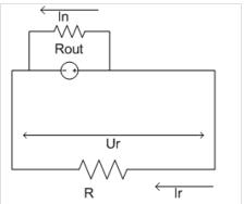
For a circuit controlled by a current source, there is also an output impedance, and output impedance is connected in parallel at both ends of DC source.
The current source delivers a constant current I, part of In is consumed by internal resistance Rout, and remaining current Ir is consumed by load R. It can be seen that voltage at load R is equal to Ur= Ir*R and two ends of internal resistance Rout. The voltage is same, i.e. Ur=Ir*R=In*Rout, and since I=Ir+In can be output, Ur=I* Rout * R /( Rout+R), load terminal power:
P=Ur*Ir=Ur2/Rout=I2*Rout*R2/(Rout+R)2= I2 *R2/(Rout+R2/Rout+2R)
It can be seen that when Rout=R, external load P is largest. Therefore, for load of a DC source, in order to obtain maximum power, it is necessary to match value of load resistance with internal resistance of current source, i.e. try to get closer to the same value.
Related
- Understanding input impedance and output impedance
- You will understand difference between input impedance and output impedance after reading this article!
- You will understand difference between input impedance and output impedance by reading this article.
- Why PCB design usually controls 50 ohm impedance
- Four ways to reduce the output "ripple and noise" of a switching power supply
- A simple understanding of op amps...
- Deep Understanding of Analog Electronics - Analog Electronics Tutorial
- One Article for Understanding PFC (Power Factor Correction)
- Optocoupler and application circuit
- What is difference between surge device, lightning arrester, leakage protection, circuit breaker and circuit breaker? Come and get knowledge
Hot Posts
 How to distinguish induction from leakage, we will teach you three tricks! Ordinary people can also learn super practical
- What is drowning in gold? Why Shen Jin?
- This is a metaphor for EMI/EMS/EMC that can be understood at a glance.
- How many types of pads have you seen in PCB design?
- Summary of Common PCB Repair Techniques
- What is three anti-paint? How to use it correctly?
- Knowing these rules, you will not get confused looking at circuit diagram.
- How to make anti-interference PCB design?
- Can diodes do this?