Location:Home Page > Archive Archive
11 classic op amp circuits
2023-03-18【Archive】
Op-amp circuits are varied and amazing, which is purpose of studying analog circuits. When analyzing how it works, if you do not understand essence, it often causes a headache. I was specifically looking for use of op-amp circuits in world, I came to a "painful decision", I hope that all colleagues who are engaged in maintenance of printed circuit boards will gain something after reading.
Looking at all books and courses on analog electronics, when introducing an op-amp circuit, it's nothing more than first giving circuit a good quality, for example, it's a non-inverting amplifier, and then deriving connection between its output and input, Then we get Vo= (1+Rf)Vi, which is an inverting amplifier, and then we get Vo=-Rf*Vi... In end, students often get impression: just remember formula! If you put circuit With a little change, then they will not find north! I interviewed at least 100 candidates for specialty of electronics with higher education and it turns out that no more than 10 people can analyze operational circuit of amplifier I gave. Another It is even more conceivable for those who have received professional education.
Today, chip-level maintenance teaches you two invincible tricks. These two tricks are clearly described in all op amp circuit textbooks. To be excellent, you need to have a deeper foundation.
Virtual short break and virtual break concept
Because voltage gain of op-amp is very large, open-loop voltage gain of general-purpose op-amp exceeds 80 dB. The output voltage of op-amp is limited, typically in range of 10 to 14 V. Therefore, differential-mode input voltage of op-amp is less than 1 mV, and two input pins are approximately equipotential, which is equivalent to a "short circuit". The greater open-loop voltage increase, closer potentials of two input terminals are equal.
"Virtual short circuit" means that when analyzing op-amp in a linear state, two input terminals can be considered as equipotential. This characteristic is called a false short circuit, called a virtual short circuit. Obviously, two input terminals cannot really be shorted.
Because input impedance of differential mode op-amp is very large, input impedance of general purpose op-amps exceeds 1 MΩ. Therefore, current flowing through op-amp's input terminal is often less than 1 µA, which is much less than external circuit current at input terminal. Therefore, two input terminals of an op-amp can generally be considered as open circuits, and greater input resistance, closer two input terminals are to open circuits.
"Virtual gap" means that, toWhen op amp is in a linear state, two input terminals can be viewed as an equivalent open circuit. This function is called a false open circuit, or virtual break for short. Obviously, two input terminals cannot be truly disconnected.
When analyzing how an op-amp circuit works, first of all temporarily forget what is single direction gain, reverse gain, what is adder, what is subtractor, what is differential input... forget about I/O ratio formulas... these things will only bother you and confuse you even more; please also ignore circuit parameters such as input bias current, common mode rejection ratio, and bias voltage for time being. which designers should consider. What we understand is an ideal amplifier (in fact, it is not difficult for maintenance and most design processes to analyze a real amplifier as an ideal amplifier).
Okay, let's take two "axes" --- "virtual brevity" and "virtual judgment" and start "getting rid of bull".
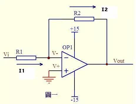
In figure 1, op-amp terminal with same direction is grounded = 0V, reverse terminal and same direction terminal are virtually shorted, so they are also 0V, input resistance of reverse input terminal is very large, virtual shutdown, almost none supply and output current, then R1 is equivalent to a series connection with R2, and current flowing through each component in series circuit is same, that is, current flowing through R1 is same as current flowing through R2. Current I1 through R1 = (Vi - V-)/R1 ...a Current I2 through R2 = (V- - Vout)/R2 ...b V- = V+ = 0 ...c I1 = I2 . .. d Solve above high school algebraic equation to get Vout = (-R2/R1)*Vi This is input to output ratio of legendary inverting amplifier.
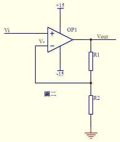
In figure 2, Vi and V- are virtual short circuits, then Vi = V- ...a Due to virtual trip, there is no current input and output at reverse input terminal, and current through R1 and R2 is Let this current is I and it is calculated in ohms. (R1+R2)/R2 This is formula of the legendary non-inverting amplifier.
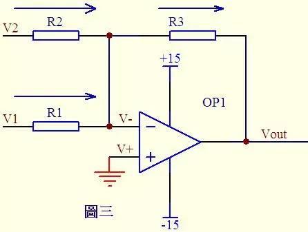
In figure 3, it is known from imaginary short circuit: V- = V+ = 0...a From imaginary trip and Kirchhoff's law, it is known that sum of currents passing through R2 and R1 is equal to current passing through R3, therefore (V1 – V-)/R1 + (V2 – V-)/R2 = (Vout – V-)/R3 ……b is substituted into formula a and formula b becomes V1/R1 + V2/R2 = Vout/R3 If R1= R2 =R3, then above formula becomes Vout=V1+V2, which is legendary adder.
(Editor's Note) Question: (V1 – V-)/R1 + (V2 – V-)/R2 = (V- – Vout)/R3 ……b Is minus sign missing in formula in fig. 3?
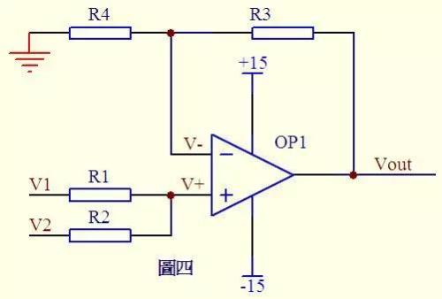
See rice. 4. Due to virtual break, no current flows through same end of op-amp, so currents flowing through R1 and R2 are equal, and currents flowing through R4 and R3 are also equal. So, (V1 – V+)/R1 = (V+ - V2)/R2 ……a (Vout – V-)/R3 = V-/R4 …b It is known from imaginary: V+ = V- …c If R1= R2, R3=R4, then V+ = (V1 + V2)/2 V- = Vout/2 can be deduced from formula above, so Vout = V1 + V2 is also an adder haha!
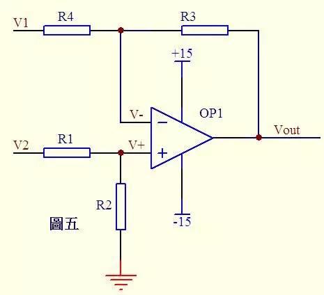
Figure 5 shows that current through R1 is equal to current through R2. Similarly, current through R4 is equal to current through R3, so (V2 – V+)/R1 = V+/R2 …a (V1 – V-)/R4 = (V- - Vout)/R3 …b If R1=R2 then V+ = V2/2 …c If R3=R4 then V- = (Vout + V1)/2 …d Knowing V+ = V-...e from virtual short, so Vout=V2-V1 This is a legendary subtractor.
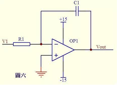
In diagram in fig. 6, it is known from virtual short circuit that voltage of reverse input terminal is equal to voltage of non-inverting terminal, and it is known from virtual judgment that current through R1 is equal to current through C1. Current through R1 i=V1/R1 Current through C1 i=C*dUc/dt=-C*dVout/dt So Vout=((-1/(R1*C1))∫V1dt Output voltage and input voltage depending on time This is a legendary integrated circuit. If V1 is a constant voltage U, above formula is converted to Vout = -U*t/(R1*C1) t is time, then output voltage Vout is a line from 0 to negative supply voltage as a function of time .
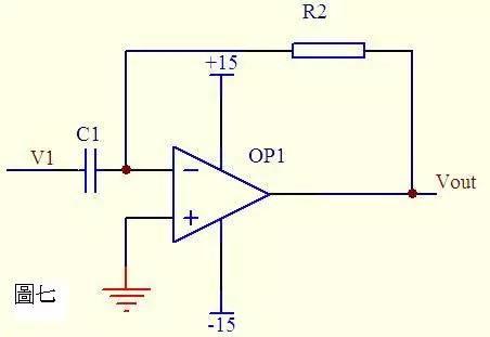
From imaginary output in Figure 7, currents passing through capacitor C1 and resistor R2 are equal, and from imaginary shortage, voltages at one and opposite ends of op-amp are equal. Then: Vout = -i * R2 = -(R2*C1)dV1/dt This is a differential circuit. If V1 is a sudden DC voltage, output Vout corresponds to a pulse in opposite direction of V1.
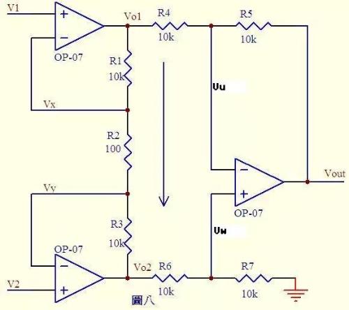
Fig. 8. Vx \u003d V1 ... a Vy \u003d V2 ... b As you know from virtual circuit, no current flows through input terminal of operational amplifier, then R1, R2 and R3 can be considered in series, through each The current of resistor is same, current I \u003d (Vx-Vy)/R2...c then: Vo1-Vo2=I*(R1+R2+R3) = (Vx-Vy) (R1+R2+R3)/R2 ......d From imaginary statement, it is known that currents flowing through R6 and R7 are equal, if R6=R7, then Vw = Vo2/2...e Similarly, if R4=R5, then Vout – Vu = Vu – Vo1, so Vu = (Vout +Vo1)/2...f is known from virtual reality, Vu = Vw...g is obtained from efg Vout = Vo2 – Vo1...h is obtained from dh Vout = (Vy –Vx)(R1+R2+R3 ) /R2 In formula above, (R1+R2+R3)/R2 is a fixed value that determines increase in difference (You-In). This circuit is a legendary differential amplifier circuit.
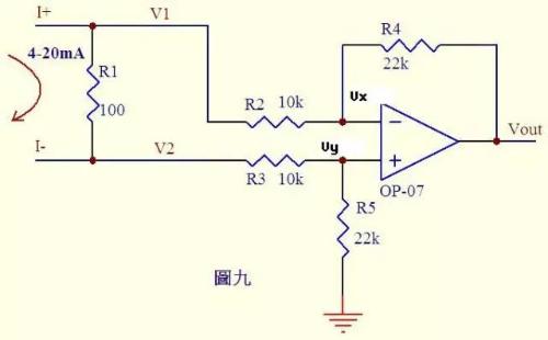
Analyze circuit that is increasingly being contacted. Many controllers receive 0-20mA or 4-20mA current from various measuring instruments. The circuit converts current into voltage and then sends it to an ADC to be converted into a digital signal. Figure 9 is such a typical circuit. As shown in Figure 4, a current of 20 mA flows through 100 Ω sampling resistor R1, and a voltage difference of 0.4-2 V will be generated across R1. through R3 and R5 are equal, and currents flowing through R2 and R4 are equal. Therefore: (V2-Vy)/R3 = Vy/R5 ......a (V1-Vx)/R2 = (Vx-Vout)/R4 ......b It is known from facts: Vx = Vy . .....c Current change from 0~20mA, then V1 = V2 + (0.4~2) ... d Substitute formula cd into formula b to get (V2 + (0.4~2)- Vy )/R2 = (Vy-Vout)/R4...e If R3=R2, R4=R5, then we get Vout = -(0.4~2)R4/R2 from e-a...f R4/R2= 22k/10k = 2.2 in Figure 9, then formula Vout = -(0.88~4.4)V, that is, 4~20mA current is converted into -0.88~-4.4V voltage, which can be sent to ADC. for processing.
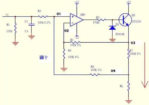
Current can be converted to voltage, and voltage can be converted to current. Figure 10 shows such a scheme. The negative feedback in above figure does not go directly through resistor, but connects emitter junction of Q1 in series. Don't think it's just a comparator. As long as it's an amplifying circuit, law of virtual short circuit and virtual break still applies!
From an imaginary statement, it is known that no current flows through input of operational amplifier, then (Vi - V1) / R2 = (V1 - V4) / R6 ... ... a Similarly, (V3 - V2) / R5 = V2 / R4 ... . ..b know V1 = V2 from imaginary short...c If R2=R6, R4=R5, then V3-V4=Vi can be obtained from formula abc. The above formula shows that voltage at both ends of R7 is equal to input voltage Vi, and current I passing through R7 =Vi/R7, if load is RL<<100kΩ, current through Rl and R7 is basically same.
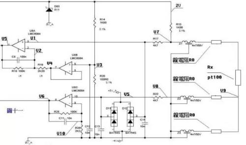
Come to complex, eh! Figure 11 is a 3-wire diagram of PT100 preamplifier.
The PT100 sensor is connected to three wires of same material, diameter and length. The connection method is shown in figure. A voltage of 2V is added to bridge circuit, composed of R14, R20, R15, Z1, PT100 and their linear resistances. Z1, Z2, Z3, D11, D12, D83 and capacitors play role of filtering and protection in circuit, which can be neglected in static analysis, Z1, Z2, Z3 can be considered as a short circuit, D11, D12, D83 and capacitors can be viewed To open way .
From dividing resistors by voltage V3=2*R20/(R14+20)=200/1100=2/11...a Due to a short circuit, voltage at pins 6 and 7 of U8B is equal to voltage at pin 5 of V4 =V3……b. From an imaginary judgment, it is known that if there is no current through 2nd pin of U8A, then currents flowing through R18 and R19 are equal. (V2-V4)/R19=(V5-V2)/R18 ……c No current flows from imaginary terminal through third terminal of U8A, V1=V7……d In bridge circuit, R15 and Z1, PT100 and line resistance When connected in series voltage obtained by connecting PT100 in series with wire resistance is added to third terminal of U8A through resistor R17, V7=2*(Rx+2R0)/(R15+Rx+2R0) … , The voltage on pin 3 is equal to voltage on pin 2, V1 =V2 ... f is obtained from abcdef, (V5-V7)/100=(V7-V3)/2.2 simplifies to V5=(102.2*V7). -100V3)/2.2 is V5 =204.4(Rx+2R0)/(1000+Rx+2R0) – 200/11 ……g The output voltage V5 in above formula is a function of Rx. resistance. The voltage drop generated across low line resistance Pt100 passes through middle line resistance, Z2, R22, and is added to 10th pin of U8C. From virtual estimate V5=V8=V9=2*R0/(R15+ Rx+2R0) …a (V6-V10)/R25=V10/R26 …b Knowing from virtual, V10=V5 …c From formula abc, V6=( 102.2/2.2)V5=204.4R0/[2.2(1000 +Rx +2R0)] ... h is a system of equations consisting of formula gh. If V5 and V6 are measured, Rx and R0 can be calculated. If Rx is known, temperature can be obtained from formula check index table pt100.
Related
- 11 classic op amp circuits
- Differences Between Industrial Control Computer Circuits and Commercial Motherboard Circuits
- A simple understanding of op amps...
- Commonly Used Diode Circuits Essential for Engineers
- Six Methods for Testing PCB Short Circuits
- List of commonly used circuits for zener diodes
- Inventory of 27 functions of capacitors in circuits
- "Recommended Collection" Simple Electronic Circuits Tutorials for Beginners
- One article eats up all rectifier and filter circuits
- Summary of questions and answers on basics of analog circuits
Hot Posts
 How to distinguish induction from leakage, we will teach you three tricks! Ordinary people can also learn super practical
- What is drowning in gold? Why Shen Jin?
- This is a metaphor for EMI/EMS/EMC that can be understood at a glance.
- How many types of pads have you seen in PCB design?
- Summary of Common PCB Repair Techniques
- What is three anti-paint? How to use it correctly?
- Knowing these rules, you will not get confused looking at circuit diagram.
- How to make anti-interference PCB design?
- Can diodes do this?