Location:Home Page > Archive Archive
Six Methods for Testing PCB Short Circuits
2023-03-26【Archive】
First, let's look at types of common PCB shorts:
A short circuit can be divided by function:
Solder short (e.g. tin joint), PCB short (e.g. residual copper, hole deflection, etc.), device short, assembly short, ESD/EOS breakdown, internal micro short circuit board layer short circuit, electrochemical short circuit (such as chemical residue, electromigration), short circuit caused by other reasons.
Short circuits can be classified according to characteristics of wiring:
Wire-to-wire short, line-to-surface short (layer), face-to-face short (between layers).
1
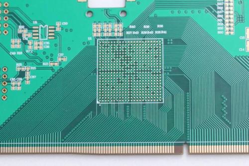
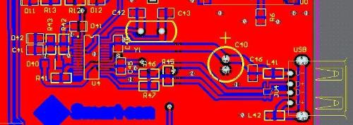
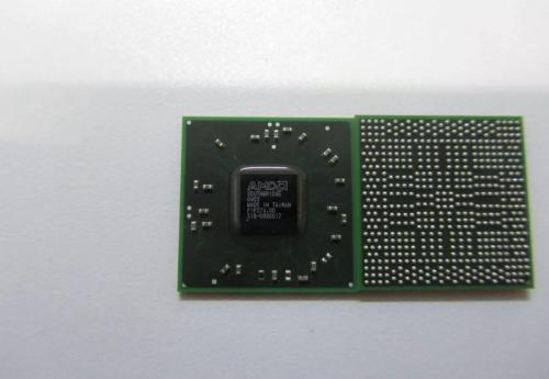
Use PC to open PCB design drawing, ignite short circuit network and see which positions are closest and easiest to connect to one element, especially note short circuit inside IC.
2
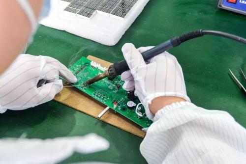
If you solder by hand, you need to develop a good habit:
1. Visually inspect PCB before soldering and use a multimeter to check if key circuits are shorted (especially power supply and ground);
2. Using a multimeter, check for a short circuit between power and ground each time you solder chip;
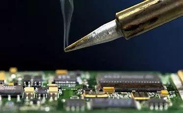
3.Do not shake soldering iron when soldering.If you throw solder on solder pins of chip (especially surface mount components), it will not be easy to detect.
3
Short circuit detected. Take cutting board (especially suitable for single layer/double layer boards), and after cutting, electrify each part of functional blocks separately and gradually dispose of them.
4
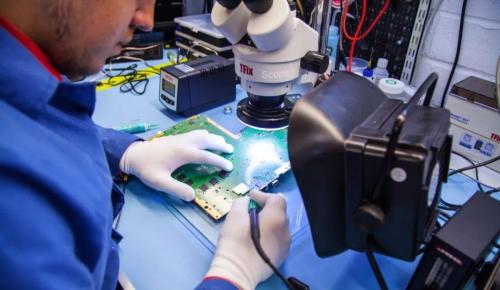
When using short circuit analysis devices for some situations in specific cases, detection efficiency of use of devices and equipment is higher, as well as higher detection accuracy.
5
If you have a BGA chip, since all solder points are covered by chip and they are not visible, and board is multilayer (more than 4 layers), it is better to separate power of each chip during design using magnetic balls or a connection with a resistance of 0 Ohm , so that when there is a short circuit between power supply and ground, turn off detection of magnetic balls, and a specific chip can be easily found. Due to difficulty of soldering a BGA, unless it is automatically soldered by machine, a little carelessness will cause adjacent power and ground solder balls to short out.
6
Be careful when soldering small surface mount capacitors, especially power filter capacitors (103 or 104), which are plentiful and can easily cause a short circuit between power and ground. Of course, sometimes, if you're unlucky, you'll run into a short circuit in capacitor itself, so it's best to test capacitor before welding.
Above: plug-in welding
When servicing circuit boards, if you encounter a short circuit in a public power supply, it is often a big headache because many devices use same power supply, and every device using this power supply is suspected of having a short. closure. If there are not many components on board, use "The "earth loosening" method can find short circuit point. If there are too many components, whether "loose ground" can find situation depends on luck.
To deal with a plug-in capacitor on PCB, you can use diagonal pliers to cut off one leg (be careful to cut it off center, don't cut it at root or on PCB). replacement chip can cut off VCC pin of power supply. When cutting a certain pin, if short circuit disappears, chip or capacitor will short circuit. If it's an SMD IC, you can use a soldering iron to melt solder on IC's power pin and lift it up to get it away from VCC power supply. After replacing short circuit element, re-weld cut off or raised part.
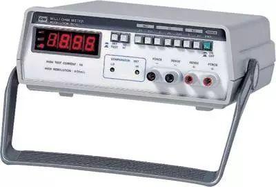
There is another, faster method, but it requires a special meter: a milliohmmeter.
We know that copper foil on a PCB also has resistance. If thickness of copper foil on PCB is 35 µm and width of printed line is 1 mm, resistance value is about 5 mΩ for every 10 mm of length. a small resistance value, it cannot be measured with a conventional multimeter, but can be measured with a milliohmmeter.
We assume that a component is shorted, and when measured with a conventional multimeter, it is 0 ohms, and when measured with a milliohmmeter, it is from tens of milliohms to hundreds of milliohms. smallest (because if it is measured at two pins of other components, resulting resistance value also includes resistance value of copper foil trace on PCB), so we compare resistance of milliohmmeter. When a resistance value is measured on a particular component (same if there is a short in solder or copper foil), component is a key suspect. With this method, you can quickly find obstacle point.
Related
- Six Methods for Testing PCB Short Circuits
- Commonly Used Diode Circuits Essential for Engineers
- List of commonly used circuits for zener diodes
- "Recommended Collection" Simple Electronic Circuits Tutorials for Beginners
- Senior engineer summarizes 10 methods for complex circuit analysis
- Differences Between Industrial Control Computer Circuits and Commercial Motherboard Circuits
- Should PCB trace angle be 90°? — Jumping guide to PCB layout pit
- 11 classic op amp circuits
- General PCB debugging skills
- Inventory of 27 functions of capacitors in circuits
Hot Posts
 How to distinguish induction from leakage, we will teach you three tricks! Ordinary people can also learn super practical
- What is drowning in gold? Why Shen Jin?
- This is a metaphor for EMI/EMS/EMC that can be understood at a glance.
- How many types of pads have you seen in PCB design?
- Summary of Common PCB Repair Techniques
- What is three anti-paint? How to use it correctly?
- Knowing these rules, you will not get confused looking at circuit diagram.
- How to make anti-interference PCB design?
- Can diodes do this?