Location:Home Page > Archive Archive
Commonly Used Diode Circuits Essential for Engineers
2023-03-18【Archive】
Summary: A diode is a very commonly used basic component. This article mainly talks about its application in circuitry. Freewheeling, Wave Detection, Voltage Doubling, Latching, Envelope Detection.
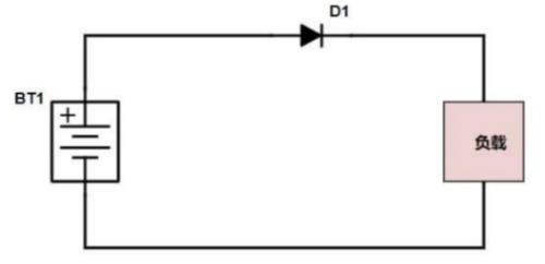
1. AntireactionIn main circuit, diode is connected in series to realize simplest and most reliable low-cost anti-reverse function circuit by using unidirectional conduction characteristic of diode. This inexpensive solution is commonly used in low current applications such as small toys. Because diode conduction will have a conduction voltage drop of 0.7V (silicon tube), if actual current is large, there will be heat loss, causing heat generation. In addition, if reverse connection voltage is very large, if reverse cut-off voltage is exceeded, diode itself will also fail, causing diode to fail, and anti-reverse connection function cannot be achieved, so it cannot protect subsequent circuit.
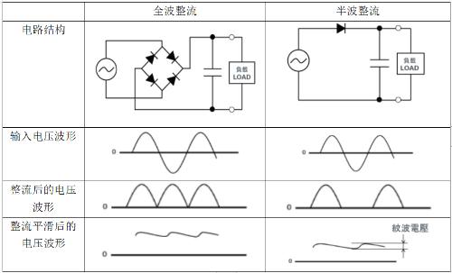
The function of rectifier circuit is to convert low-voltage AC output from AC step-down circuit into unidirectional pulsating DC current. This is process of rectifying alternating current. The rectifier circuit is mainly composed of rectifier diodes. . The voltage after rectifier circuit is no longer an alternating voltage, but a mixed voltage containing direct and alternating voltage, which is commonly called unidirectional pulsating direct voltage.
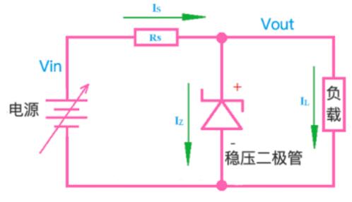
A diode with a voltage stabilization effect is called a Zener diode, and its English name is a Zener diode, also known as a Zener diode. By using reverse breakdown state of PN junction, current can be varied over a wide range while voltage remains almost unchanged. The basic structure of circuit is shown in figure below.
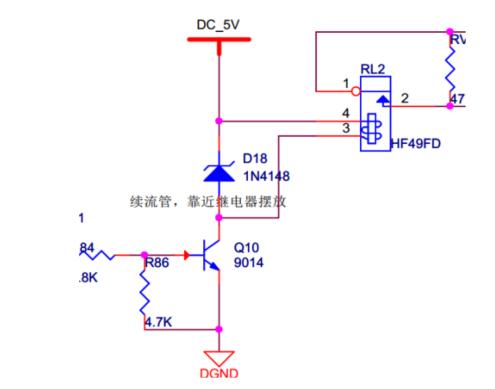
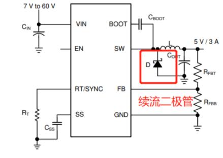
Freewheeling diodes are connected in parallel at both ends of coil (inductive components). When coil passes current, it generates an induced electromotive force at both ends. When current is gone, its induced electromotive force will create a reverse voltage for original components in circuit. When reverse voltage is higher than reverse breakdown voltage of original, it will damage original, such as a triode. The flyback diode is connected in parallel to both ends of line. When current flowing through coil disappears, induced electromotive force generated by coil will be consumed through circuit formed by diode and coil. The entanglement protects safety of other original components in chain. The general structures of circuit are as follows.
Or a reverse diode in BUCK circuit
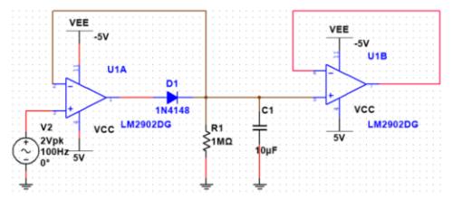
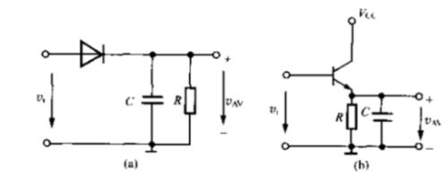
A peak detection circuit determines maximum amplitude value of input signal. How it works: when input voltage amplitude is greater than forward voltage of diode, diode turns on, and output voltage is added to capacitor C1, and two ends of capacitor are charged. Thereafter, when input voltage amplitude is lower than previous input voltage amplitude, diode is in a reverse bias cutoff state. During this time, voltage across capacitor remains largely unchanged; voltage at terminal (that is, forward voltage applied to diode) diode can conduct.
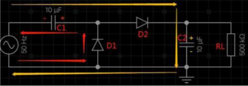
The figure below shows circuit diagram of a dual voltage circuit and its workflow is roughly analyzed as follows:
During negative half cycle of power supply, diode D1 is on and D2 is off. Current flows from lower end of power supply through D1 and C1 returns to power supply. Capacitor C1 is positive on right and negative on left, as shown by red arrow in figure below. In positive half-cycle of power supply, voltage across capacitor C1 is superimposed on voltage of power supply, so that diode D2 is on and diode D1 is off. Capacitor C2 is positive and negative, and peak voltage can be twice peak voltage of power supply. The current trend during cycle is indicated by orange arrow. in figure below.
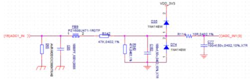
Some ADC detection circuits use two diodes for clamp protection. The principle is very simple. 0.7V is conduction voltage drop across D1 and D2. When voltage on Vin is greater than or equal to 3.3V + 0.7V, D35 conducts through, Vout will be fixed at 4V; when Vin is less than or equal to -0.7V, Vout will be fixed at around -0.7V.
The structure of schema is shown below. The design point is that RC time constant must be much larger than carrier period and much smaller than baseband period.
Related
- Commonly Used Diode Circuits Essential for Engineers
- List of commonly used circuits for zener diodes
- Analysis and comparison of 6 most commonly used DC power supply circuits
- A list of some of the tools commonly used by electronic engineers.
- Anti-reverse connection is very important, make good use of these 4 commonly used circuits
- must read! Electronics Engineers Must Master 7 Common Interfaces in Circuits
- Countdown of 8 most commonly used diodes
- Commonly Used Peripheral Diagrams, Hardware Design Reference and Precautions
- 13 Commonly Used Basic Schema Formulas Beginners Should Read
- Commonly used models of rectifier diodes, what are important parameters?
Hot Posts
 How to distinguish induction from leakage, we will teach you three tricks! Ordinary people can also learn super practical
- What is drowning in gold? Why Shen Jin?
- This is a metaphor for EMI/EMS/EMC that can be understood at a glance.
- How many types of pads have you seen in PCB design?
- Summary of Common PCB Repair Techniques
- What is three anti-paint? How to use it correctly?
- Knowing these rules, you will not get confused looking at circuit diagram.
- How to make anti-interference PCB design?
- Can diodes do this?