Location:Home Page > Archive Archive
"Recommended Collection" Simple Electronic Circuits Tutorials for Beginners
2023-05-10【Archive】
In general, success of early projects plays a decisive role in career of an engineering student. Many students give up electronic devices after failing on their first try. After several failures, students mistakenly assume that projects that work today may not work tomorrow. Therefore, we recommend that beginners start with following projects, which will give results on first try and give strength to your own work. Before proceeding, you must know how to work and use a breadboard. This article presents top 10 simple electronic circuits for engineering students, suitable for beginners and mini-projects, but not for last year's projects. The following schemas apply to base and subclasses.
A primer on simple electronic circuits for beginners
The list of top 10 simple electronic circuits discussed below is very helpful for beginners as they practice, these circuits are designed to help with complex circuits.
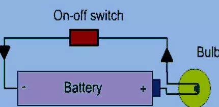
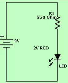
DC lighting circuit
DC power supplies are used for small LEDs with two terminals: an anode and a cathode. The anode is +ve and cathode is -ve. Here, a lamp is used as a load, which has two terminals, for example, positive and negative. The positive terminal of flashlight is connected to anode terminal of battery, and negative terminal of battery is connected to negative terminal of battery. A switch is connected between wires to supply a constant supply voltage to the LED light bulb.
Rain Warning
The next rainwater circuit is used to give an alarm when it rains. This type of chain is used in homes to protect linens and other items that are exposed to rain when they spend most of their time at home working. The components needed to build this circuit are probes. 10K and 330K resistors, BC548 and BC 558 transistors, 3V battery, 0.01mF capacitor and speaker.
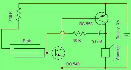
Rain warning
Whenever rain water comes into contact with sensor in above circuit, a current flows through circuit which activates transistor Q1 (NPN) and transistor Q1 activates transistor Q2 (PNP). So transistor Q2 turns on and then current flows through speaker, creating a buzzing sound. This process is repeated over and over until probe comes into contact with water. The oscillation circuit built into above circuit changes frequency of tone, so tone can be changed.
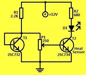
Simple temperature monitor
When battery voltage is greater than 9 volts, voltage across base-emitter terminals will be same. This keeps transistor and LED off. When battery voltage drops below 9V due to usage, base voltage of transistor T1 drops while its emitter voltage stays same because capacitor C1 is fully charged. During this phase, base terminal of transistor T1 goes to +ve and turns on. Capacitor C1 is discharged through LED.
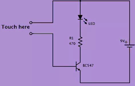
Touch sensor outline
The touch sensor circuit consists of three components, such as a resistor, a transistor, and an LED. Here, resistor and LED are connected in series with positive power supply at collector terminal of transistor. Choose a resistor to set LED current to around 20mA. Now, given connections of two open ends, one to +ve source and other to base of transistor. Now touch two wires with your finger. Touch these wires with your finger and LED will light up!
Touch sensor outline
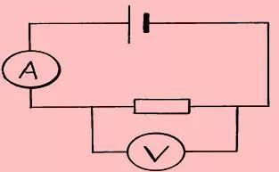
Multimeter Schematic
A multimeter is a necessary simple basic circuit used to measure voltage, resistance, and current. It is also used to measure DC and AC parameters. A multimeter consists of a galvanometer connected in series with a resistor. The voltage in a circuit can be measured by placing probes of a multimeter over circuit. Multimeters are mainly used to check continuity of motor windings.
Multimeter schematic
LED flash circuit
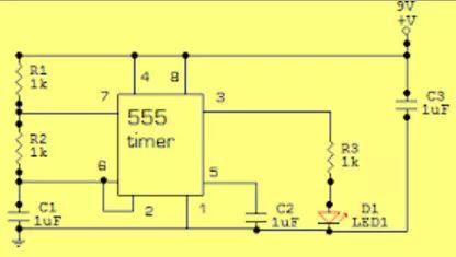
The LED flash circuit configuration is shown below. The following circuit uses some of most popular components such as 555 timers and integrated circuits. This circuit will flash LED periodically.
LED flash diagram
From left to right in circuit, a capacitor and two transistors set time and turn LED on or off. By changing time it takes for capacitor to charge to activate timer. The IC 555 timer is used to determine how long LED stays on and off. It contains a complex circuit inside, but since it is packaged in an integrated circuit. Two capacitors are located to right of timer, they are necessary for correct operation of timer. The last part is LED and resistor. The resistor is used to limit current on LED. So it won't get damaged.
Invisible burglar alarm
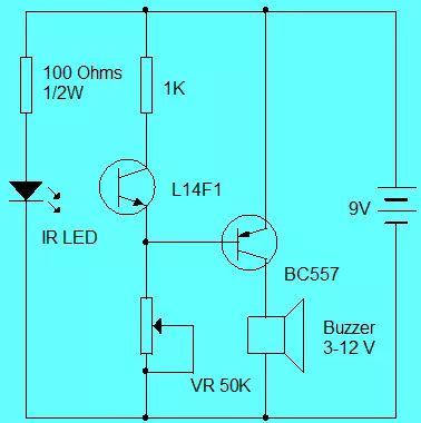
The invisible burglar alarm circuit consists of a phototransistor and an infrared LED. The alarm will not beep if there are no obstacles in way of infrared radiation. When someone passes through infrared port, a beep sounds. If phototransistor and infrared LED are packed in a black tube and connected correctly, range of circuit is 1 meter.
Invisible burglar alarm
When IR beam falls on L14F1 phototransistor, it makes BC557 (PNP) non-conductive, in which case buzzer will not work. When infrared beam turns off, phototransistor turns off, allowing PNP transistor to work and buzzer to sound. Attach phototransistor and IR LED on reflective side in correct position so that buzzer does not sound. Adjust variable resistor to set bias for PNP transistor. Other phototransistors can be used instead of LI4F1, but L14F1 is more sensitive.
LED Circuit
A light emitting diode is a small component that emits light. Using LEDs has many advantages as they are very cheap, easy to use and we can easily tell if a circuit is working by its indication.
LED diagram
Under forward bias conditions, holes and electrons move back and forth across junction. In process, they will combine or otherwise offset each other. Over time, if an electron moves from n-type silicon to p-type silicon, that electron connects with a hole and disappears. It produces an entire atom and is more stable, so it will generate a small amount of energy in form of photons.
Under reverse bias conditions, a positive power supply will absorb all electrons present in junction. And all holes will be directed to negative terminal. Thus, charge carriers deplete junction, and no current flows through it.
Anodes are long needles. This is pin that connects to most positive voltage. The cathode pin must be connected to negative voltage itself. They must be properly connected for LED to work.
A simple light-sensitive transistorized metronome
Any device that plays regular rhythmic syllables (beats, clicks) we call a metronome (set beats per minute). The scales here represent fixed, regular auditory impulses. Synchronized visual movements such as pendulum are also included in some metronomes.
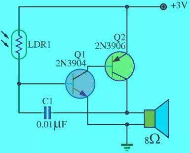
Simple photosensitive transistorized metronome
This is a simple light sensitive transistorized metronome circuit. This circuit uses two types of transistors, namely transistor numbers 2N3904 and 2N3906, to form original frequency circuit. The sound from speaker will increase and decrease due to frequency of sound. LDR is used in this circuit. LDR stands for Light Dependent Resistor, we can also call it Light Resistor or Photocell. LDR is a light controlled variable resistor.
If intensity of incident light increases, LDR resistance will decrease. This phenomenon is called photoconductivity. When a dim light flash reaches LDR in a dark room, it receives light, then LDR resistance drops. This will raise or affect frequency of source, frequency of audio circuit. Solid wood constantly touches music with a change in frequency in circuit. See diagram above for more information.
Related
- "Recommended Collection" Simple Electronic Circuits Tutorials for Beginners
- Experience in recognition of circuit diagrams of electronic circuits and method of circuit analysis
- Commonly Used Diode Circuits Essential for Engineers
- Six Methods for Testing PCB Short Circuits
- List of commonly used circuits for zener diodes
- Explain in detail classification of more than a dozen types of "recommended collection" capacitors
- Differences Between Industrial Control Computer Circuits and Commercial Motherboard Circuits
- 11 classic op amp circuits
- Principle of electronic switch to realize overcurrent protection
- Inventory of 27 functions of capacitors in circuits
Hot Posts
 How to distinguish induction from leakage, we will teach you three tricks! Ordinary people can also learn super practical
- What is drowning in gold? Why Shen Jin?
- This is a metaphor for EMI/EMS/EMC that can be understood at a glance.
- How many types of pads have you seen in PCB design?
- Summary of Common PCB Repair Techniques
- What is three anti-paint? How to use it correctly?
- Knowing these rules, you will not get confused looking at circuit diagram.
- How to make anti-interference PCB design?
- Can diodes do this?