Location:Home Page > Archive Archive
One Article for Understanding PFC (Power Factor Correction)
2023-03-18【Archive】
What is Power Factor Correction? What is power factor correction?
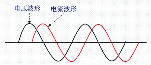
Power factor correction. In 1950s, improvements were made to eliminate inefficiency in powering AC devices with inductive loads due to phase mismatch between voltage and current (Figure 1). Method (because current of inductive load lags applied voltage, load on power supply line increases due to different phases of voltage and current, resulting in a decrease in efficiency of power supply line, which requires a parallel connection of a capacitor on an inductive electrical appliance to adjust power consumption. Voltage phase characteristics and current of device, for example: 40 W fluorescent lamp used at that time had to be connected in parallel with a 4.75 uF capacitor).
Using a capacitor in parallel with an inductive load, using current characteristic leading voltage of capacitor to compensate for lagging current voltage of inductor, to make overall characteristic close to resistive, thereby improving low efficiency is called power factor correction (AC power factor can be expressed as value of cosine function cosφ of phase angle between supply voltage and load current).
Picture 1
Voltage and current waveforms in power lines with inductive loads
Since 1980s, a large number of high-efficiency switching power supplies have been used in electrical appliances. Since switching power supplies use a large-capacity filter capacitor after rectification, load characteristics of electrical appliances are capacitive. caused 220V AC to power appliance, due to charging and discharging of filter capacitor, DC voltage at both ends of filter has a slight sawtooth ripple.
The minimum value of voltage across filter capacitor is far from zero and not far from its maximum value (peak ripple value). According to unidirectional conduction of rectifier diode, only when instantaneous value of AC mains voltage is higher than filter capacitor voltage, rectifier diode will be turned on by forward bias, and when instantaneous value of AC voltage, input voltage is lower than filter capacitor voltage. When energized, rectifier diode turns off due to reverse bias.
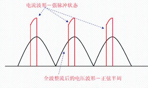
That is, during each half-cycle of AC mains voltage, diode only conducts current near its peak value. Although AC input voltage remains approximately sinusoidal, AC input shows high amplitude peaks, as shown in Figure 2. This highly distorted current waveform contains a large amount of harmonic content causing a severe drop in line power factor.
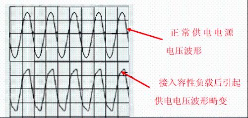
During positive half cycle (1800) conduction angle of rectifier diode is much less than 1800 or even only 300-700. Due to requirement to provide load power during an extremely narrow conduction angle. The conduction current makes power supply current in power circuit in a pulsed state, which not only reduces efficiency of power supply, but more seriously, causes severe distortion of AC voltage waveform when capacitance of power line is insufficient or load of circuit is large (Fig. 3), and generate multiple harmonics, thereby interfering with normal operation of other electrical appliances (this is problem of electromagnetic interference-EMI and electromagnetic compatibility-EMC).
Picture 2
As electrical appliances in past moved from inductive loads (early televisions, radios, etc., all used inductive power transformer devices) to capacitive loads with rectifiers and filter capacitors, point of power factor compensation is not only . is problem of different phases of voltage and current of power supply. What is more serious is solution of electromagnetic interference (EMI) and electromagnetic compatibility (EMC) problems caused by strong current pulse state of power supply.
This is a new technology developed at end of last century (its background is associated with rapid development and widespread use of switching power supplies). Its main purpose is to solve electromagnetic interference (EMI) and electromagnetic compatibility (EMC) problems caused by severe current waveform distortion caused by capacitive loading. Therefore, current power factor correction technology is completely different from former power factor correction technology. It is applied to distort non-sinusoidal current waveform, causing AC line current to follow path of instantaneous change in voltage waveform, and keeping current and voltage in same phase, so that system Purely resistive technology (line current waveform correction technology) appears, it is PFC (power factor correction).
Thus, modern PFC technology has completed correction of current waveform, and also solved problem of same phase of voltage and current.
Picture 3
For above reasons, it is necessary to add a correction circuit to correct load characteristics of electrical appliances with capacitive loads that require a power consumption of more than 85W (some data show more than 75W) so that load characteristics are close to resistive (voltage and current waveforms are in same phase, and waveforms are similar). This is a state-of-the-art power factor correction (PFC) circuit.
The dangers of capacitive loads
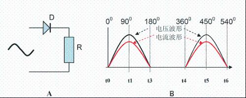
The following figure 4 shows a half-wave rectifier circuit without a filter capacitor, and figure 5 shows a half-wave rectifier circuit with a large filter capacitor. Based on these two circuits, we analyze waveforms of currents in two circuits.
Picture 4
D in A is rectifier tube and R is load. 4B is a waveform diagram of voltage and current in circuit when circuit is connected to AC.
During (00~1800) t0~t3: voltage is zero at time t0 and current is zero, voltage reaches its maximum value at time t1, and current also reaches its maximum value, and voltage is zero and current is zero at time time t3. (diode conductivity 1800)
At (1800~3600) t3~t4: Time: The diode is reverse biased and has no voltage and no current. (diode off)
During (3600~5400) t4~t6: voltage is zero at time t4 and current is zero, voltage reaches its maximum value at time t5, and current also reaches its maximum value, and voltage is zero and current is zero at time time t6. (diode conductivity 1800)
Conclusion: In a rectifier circuit without a filter capacitor, voltage and current of supply circuit are in phase, and conduction angle of diode is 1800. For supply line, circuit is a purely resistive load characteristic. .
Picture 5
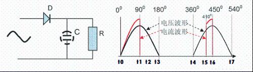
D in figure 5A is rectifier, R is load, C is filter capacitor. Fig. 5V is a waveform diagram of voltage and current in a circuit when circuit is connected to AC.
At time (00~1800)t0~t3: voltage is zero at time t1 and current is zero, and voltage reaches its maximum value at time t1, and current also reaches its maximum value, because at this time load R power is supplied, and also power is supplied to capacitor C. Charging, so amount of current is relatively large. At time t1, due to charging of capacitor C, voltage Uc of capacitor reaches peak value of AC input. Since voltage of capacitor cannot change suddenly, voltage on right side of diode is Uc for t1~t3, and voltage on left side gradually changes from peak value at time t2, drops to zero, diode is reverse biased and turned off within t1~t3, and current during this period is zero. (In positive half-cycle of first AC after addition of filter capacitor C, conduction angle of diode is 90°)
During (1800~3600) t3~t4: The diode is reverse biased and has no voltage and no current. (diode off)
During (3600~4100)t4~t5: Since diode is reverse biased during t3~t4, C is not charged, voltage at C is discharged through load, and voltage gradually drops (the drop is determined by capacitance C and resistance R. If capacitance C is large enough and resistance R is large enough, its Uc will fall very slowly.) Although voltage on left side of diode gradually increases during t4~t5 due to slow discharge of Uc on right side of diode. The voltage Uc is still greater than on left side and diode is still reverse biased and off.
At (4100~5400) t5~t7: The voltage on left side of diode rises and exceeds voltage on right side at time t5. The diode turns on to supply power to load and charge C. The current flowing through diode is relatively large. At time t6, voltage on left side of diode gradually decreases again as Uc charges back to its maximum value and diode enters reverse bias cutoff at time t6~t7.
Conclusion: In a filter capacitor rectifier circuit, voltage and current waveforms of power supply circuits are completely different. Determined by filter capacitor time constant C). For power line of this circuit, due to large voltage drop on line during a very short period of a strong current pulse (especially for a power line with a large internal resistance), voltage shape of power line is distorted, and a large pulse. Higher harmonics can cause strong interference to other electrical appliances.
How to perform power factor correction?
Power Factor Correction (PFC)
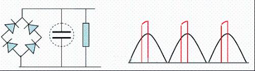
Because TV we are currently using uses a high-efficiency switching power supply, internal input part of switching power supply uses a diode full-wave rectifier and a filter circuit without exception, as shown in Fig. 6A and its voltage and current curves are shown in fig. 6A 6B.
Picture 6 A B
In order to suppress current waveform distortion and improve power factor, modern electrical appliances with large power (more than 85W) and switching power supply (capacitive load) need to take PFC measures, PFC has active PFC and passive PFC in two ways.
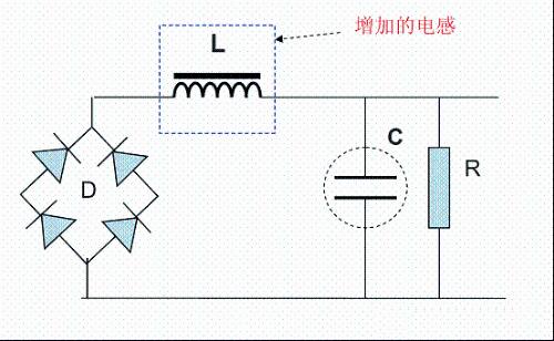
Currently, some manufacturers do not use correction circuits consisting of active devices such as transistors. Typically, it consists of passive components such as diodes, resistors, capacitors, and inductors. For higher power TVs designed in past, an inductor (selected appropriately) is added between rectifier bridge unit and filter capacitor. Inductance), using characteristic that inductor current cannot suddenly change, to smooth out fluctuation of a strong capacitor charging pulse, improve power line current waveform distortion and voltage leading characteristic of inductor current also compensates for current characteristic of filter capacitor leading voltage, so that power factor , electromagnetic compatibility and electromagnetic interference are improved, as shown in Figure 7.
Picture 7
Although this circuit is simple, you can just add a suitable inductance (choose L and C values appropriately) on a non-PFC device designed at an early stage to implement PFC function, but this is simple, inexpensive passive ripple on PFC output is relatively is large, DC voltage at both ends of filter capacitor is also low, ability to correct current distortion and power factor compensation is very poor, and quality control of L winding and iron core is not good, it will cause serious interference to picture and sound, and it can only be temporary measure at an early stage without PFC equipment, allowing to enter market.
Active PFC Circuit Principle
Active power factor correction has a very good effect. It can basically completely eliminate distortion of current waveform, and voltage and current phases can be controlled to ensure consistency. It can basically completely solve power factor, electromagnetic compatibility, electromagnetic interference problem, but circuit is very complex. The main idea is to remove filter capacitor after assembling 220V rectifier bridge (to eliminate current waveform distortion and phase change caused by charging capacitor), and after removing filter capacitor, "Chopper" circuit turns pulsating DC into high frequency (about 100K) AC, and after rectification and filtering, DC voltage is then fed to a normal PWM switching power supply. →direct current→alternating current→direct current.
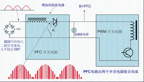
The basic principle of Active Power Factor Correction is to add a DC breaker circuit between SMPS rectifier circuit and filter capacitor (Figure 8 (Optional SMPS)). The rectifier circuit is not directly connected to capacitance filter, so it is a purely resistive load on power line, and its voltage and current waveforms are in same phase and have same phase. The chopper circuit also works as a switching power supply. Thus, an active power factor correction switching power supply is a dual switching power supply switching power supply circuit, which consists of a chopper (let's call it: "switching power supply with power factor correction") and a regulated switching power supply (we will call it later: "switching power supply with PWM"), switching power supply").
Picture 8
Chopper part (PFC switching power supply)
After rectifying rectifier diode, no filter capacitor is added, and unfiltered pulsating positive half-cycle voltage is used as chopper power. 9:
1. The current waveform is discontinuous, its envelope coincides with voltage waveform, and phase of envelope and voltage waveform are in phase.
2. Due to chopping effect, half-wave pulsating DC power becomes high-frequency (determined by chopping frequency, about 100kHz) "AC". A switching regulated PWM power supply is used.
3. From external power supply point of view, power system ensures same phase of AC voltage and AC current, and waveform of voltage and current is consistent with sinusoidal waveform, which not only solves problem of power factor compensation. , but also solves problem of electromagnetic compatibility (EMC) and electromagnetic interference (EMI).
The high-frequency "AC" power is rectified by rectifier diode and filtered to become DC voltage (power supply) to power next stage switching PWM power supply. The DC voltage in some materials is called: B+PFC (in case of TPW-4211). The output voltage of B+PFC breaker is usually higher than +300 V after initial rectification and filtering of 220 V AC. The reason for high voltage is chosen, diameter of inductor wire small, line voltage drop is small, filter capacitor capacitance is small, filter effect is good, and there are many advantages, such as low downstream requirements. PWM switch tube. The black color is voltage waveform and red dotted line is the current envelope waveform.
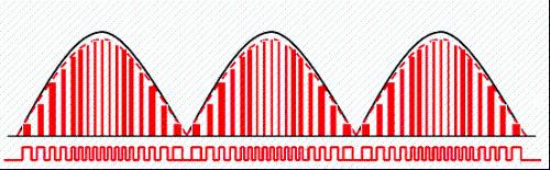
Picture 9
Currently, in PFC switching power supply part, breaker tube (K), which acts as a switch, has two modes of operation:
1. Continuous Conduction Mode (CCM): The operating frequency of switching tube is constant, and duty cycle (coefficient) of conduction changes with amplitude of interrupted voltage, as shown in Figure 10, T1 and T2. in figure The position is: T1 is in low voltage region of cutoff voltage (half cycle), T2 is in region of high voltage cutoff voltage, T1 (time) = T2 (time) From In figure, we can see that all times of switching cycles are all equal, and this means that for any amplitude of interrupted voltage, operating frequency of interrupter lamp remains unchanged, as can be seen from figure 10; duty cycle of each interrupt cycle in high voltage region and low voltage region is different (T1 and T2 times are same, but rising pulse width is different), when cutoff voltage is zero (no voltage), cutoff frequency remains unchanged, so this is called continuous conduction mode ( CCM) This mode is generally applied to 250W to 2000W equipment.
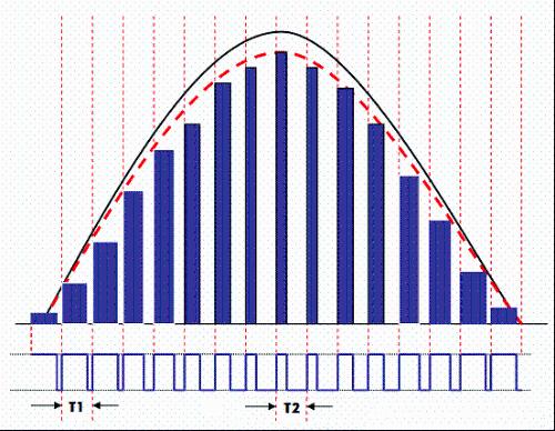
Picture 10
2. Discontinuous Conduction Mode (DCM): The operating frequency of chopper switching tube varies with amount of interrupted voltage (on and off times are same in each switching cycle. As shown in Figure 11). : The times of T1 and T2 are different, and it also reflects that interrupt frequency changes according to change in voltage amplitude. The interrupt voltage is "zero" and switch stops (oscillation stops), so it is called discontinuous conduction mode. (DCM), that is, input voltage breaker tube works, but input voltage breaker tube does not work. Usually used in low power devices below 250W.
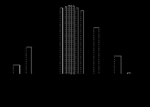
Picture 11
(3) Critical Conductive Mode (CRM) or Transient Mode (TCM):
The work is between CCM and DCM, and work is closer to DCM mode. After last conduction period, before next conduction period, inductor current will drop to zero and frequency will vary with line voltage and load.
Advantages: cheap chip, simple design, no switch conduction loss, boost diode selection is not critical;
Cons: Potential EMI problems due to frequency variation require a well designed input filter.
Related
- One Article for Understanding PFC (Power Factor Correction)
- Understand Current Detection Circuit in One Article
- One article eats up all rectifier and filter circuits
- The best switching circuit design process for power supplies is a must for engineers!
- Is printed circuit board covered with copper very “up to mark”? One article to help you get practical guidelines and norms
- A simple understanding of op amps...
- Understanding input impedance and output impedance
- Deep Understanding of Analog Electronics - Analog Electronics Tutorial
- Power port lightning protection circuit
- An article to understand "advantages" and "cons" of solid capacitors
Hot Posts
 How to distinguish induction from leakage, we will teach you three tricks! Ordinary people can also learn super practical
- What is drowning in gold? Why Shen Jin?
- This is a metaphor for EMI/EMS/EMC that can be understood at a glance.
- How many types of pads have you seen in PCB design?
- Summary of Common PCB Repair Techniques
- What is three anti-paint? How to use it correctly?
- Knowing these rules, you will not get confused looking at circuit diagram.
- How to make anti-interference PCB design?
- Can diodes do this?