Location:Home Page > Archive Archive
Diode switching circuit and troubleshooting, one complete wizard
2023-05-06【Archive】
A switch circuit is a commonly used functional circuit, such as a switch in a lighting circuit in a house, a power switch in various household appliances, etc.
There are two types of switches in switching circuits:
(1) Mechanical switches using mechanical switches as switching circuit components.
(2) Electronic switches, so-called electronic switches, do not use mechanical switching elements, but use devices such as diodes and triodes to form switching circuits.
1. Description of diode switching characteristics
Switching diodes are same as ordinary diodes, and they are also a PN junction structure. The difference is that switching performance of this diode should be better.
When a forward voltage is applied to switching diode, diode is in conductive state, which is equivalent to on state of switch; when reverse voltage is applied to switching diode, diode is in off state, which is equivalent to switch off state. The on and off states of diode complete on and off functions.
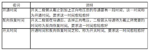
Switching diodes use this characteristic, and due to manufacturing process, switching characteristics are better, that is, switching speed is faster, PN junction junction capacitance is smaller, internal turn-on resistance is smaller. , and resistance in off state is large. . Table 9-41 shows concept of switching times.
Table 6.19 Description of switching time concept
2. Typical operating principle of a diode switching circuit
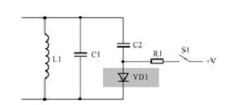
Switching electronic circuits made up of diodes come in a variety of forms, as shown in fig. 9-46 for a typical diode switching circuit.
Watching this circuit, you can become familiar with following aspects that will make it easier to understand how circuit works:
(1) Understanding function of this device diagram is first step. From circuit shown in Figure 8-14, it can be seen that inductor L1 and capacitor C1 are connected in parallel, which is obviously an LC parallel resonant circuit, which is main function of this unit circuit. After clarifying this point, we can know that other components in circuit should be an auxiliary component around that main function, an extension or addition to circuit's main function, etc. This way of thinking can easily analyze function of components in circuit.
(2) C2 and VD1 form a series circuit, and then they are connected in parallel with C1. From this circuit structure, we can conclude that function of branch of C2 and VD1 is to change parallel connection with capacitor C1 through this branch. Reason such a judgment is that total capacitance of branches C2 and VD1 is connected in parallel with C1, and oscillation frequency of LC-parallel resonant circuit formed with L1 is changed. So this is a circuit that changes frequency of an LC parallel resonant circuit.
The following points are explained by analyzing diode electronic switch circuit:
(1) In a circuit, C2 and VD1 are connected in series. According to characteristics of a series circuit, C2 and VD1 are either connected to circuit at same time or disconnected at same time. If only C2 needs to be connected in parallel with C1, C2 can be connected directly in parallel with C1, but VD1 diode is in series, indicating that VD1 controls connection and disconnection of C2.
(2) According to conductance and cutoff characteristics of diode, VD1 is turned on when C2 is required to be connected to circuit, and VD1 is turned off when C2 is not required to be connected to circuit. This diode working mode is called switching mode, such a circuit is called a diode switching circuit.
(3) The conduction and cutoff of diode must be controlled by voltage. In circuit, anode VD1 is connected to constant voltage terminal V through resistor R1 and switch S1. This voltage is control voltage. diode.
(4) Switch S1 in circuit is used to control whether operating voltage V is connected to circuit. From circuit of switch S1, it is easier to confirm that diode VD1 is operating in switch state, since turning S1 on and off controls conduction and cutoff of diode. As shown in Table 9-42, this is a description of working principle of diode electronic switch circuit.
Table 9-42 Explanation of working principle of diode electronic switch circuit
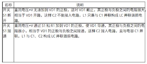
In above two states, due to different capacitances in LC parallel resonant circuit, in one case only C1, and in other case C1 and C2 are connected in parallel, and resonant frequency of parallel LC resonant circuit under condition of different capacitance is different. Therefore, real function of VD1 in circuit is to control resonant frequency of LC-parallel resonant circuit.
The following two points are explained in detail when analyzing diode electronic switch circuit:
(1) When there is a switch in circuit, circuit analysis takes two cases of on and off as examples and analyzes working state of circuit accordingly. So when a switch appears in a circuit, it can provide insights for circuit analysis.
(2) The signal in LC parallel resonant circuit is added to positive pole of VD1-C2, but because amplitude of signal in resonant circuit is relatively small, amplitude of positive half-wave signal added to positive pole of VD1 is very small, which does not ensure conduction of VD1.
3. Fault detection method and circuit fault analysis
As shown in Figure 9-47, this is circuit diagram for connecting switching diode in detection circuit. When switch is turned on, measure DC voltage drop across diode VD1. It should be 0.6V. If it is much less than this voltage value, it means that VD1 has a short circuit. If voltage value is much less than this value, it means that VD1 has an open circuit. In addition, if there is no obvious short circuit or open circuit VD1, you can measure its direct resistance with a multimeter, it should be small, otherwise it’s not good if direct resistance is too large.
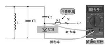
If switching diode in this circuit is open or shorted, oscillation frequency cannot be adjusted. With switching diode open, capacitor C2 cannot be connected to circuit, and oscillation frequency increases at this time; when switching diode is short-circuited, capacitor C2 is always connected to circuit, and oscillation frequency decreases at this time.
4. Analysis of principle of operation of such schemes
Analysis of principle of operation of such schemes
Related
- Diode switching circuit and troubleshooting, one complete wizard
- Analysis of damping RC circuit of a switching power supply "haberdashery"
- Is printed circuit board covered with copper very “up to mark”? One article to help you get practical guidelines and norms
- The best switching circuit design process for power supplies is a must for engineers!
- Understand Current Detection Circuit in One Article
- What is difference between TVS tube and zener diode?
- Optocoupler and application circuit
- What is difference between surge device, lightning arrester, leakage protection, circuit breaker and circuit breaker? Come and get knowledge
- Experience in recognition of circuit diagrams of electronic circuits and method of circuit analysis
- The most complete test of iron 5 processes, one less will not work
Hot Posts
 How to distinguish induction from leakage, we will teach you three tricks! Ordinary people can also learn super practical
- What is drowning in gold? Why Shen Jin?
- This is a metaphor for EMI/EMS/EMC that can be understood at a glance.
- How many types of pads have you seen in PCB design?
- Summary of Common PCB Repair Techniques
- What is three anti-paint? How to use it correctly?
- Knowing these rules, you will not get confused looking at circuit diagram.
- How to make anti-interference PCB design?
- Can diodes do this?