Location:Home Page > Archive Archive
Optocoupler and application circuit
2023-03-18【Archive】
isolating devices commonly used in electrical engineering include optocouplers, relays, and transformers.
An optocoupler is a flow controlled component that uses light as a medium to transmit signals: Electric → Light → Electricity, input end is an LED and output end is a photosensitive semiconductor. The main use of optocouplers is isolation, which is often used in systems with no common ground between input and output. Therefore, withstand voltage between input and output can reach thousands of volts.
Many communication modules are also isolated with optocouplers, making it easy to implement a connection between different systems without having to consider if they share same ground.
For example, fig. 1 is an optocoupler (low power) control relay, in order for optocoupler to effectively drive relay, output impedance must be small, so input end current must be relatively large, specific reason See analysis below.
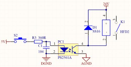
Figure 1. Optocoupler control relay
As shown in Figure 2, switch signal is injected into microcontroller through isolation of optocoupler. In figure, 24V and 3.3V are not common ground, and digital voltage of control system is limited, so generally use 24V or 12V switching power supply as switching signal power supply.
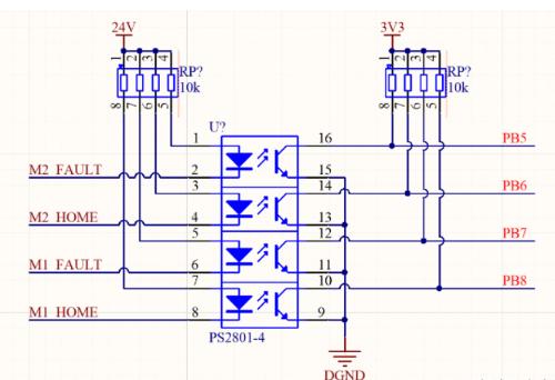
Figure 2. Inlet and outlet isolation
The above two common applications looks simple, but to properly use an optocoupler, you need to know what is relationship between input and output of an optocoupler?
Optocouplers are divided into linear optocouplers and non-linear optocouplers. In common practical applications, there are more linear optocouplers because linear optocouplers can replace non-linear optocouplers. Now linear optocouplers (PS2561A) perform following experiment, Experience charm of TA from other side.
As shown in Fig. 3, adjust IF input current of optocoupler and measure output impedance CE.
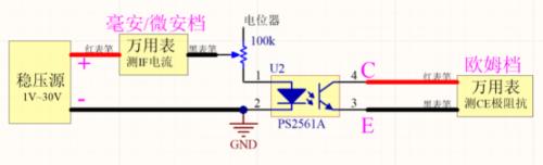
Figure 3: Experiment on relationship between input current IF and output impedance CE
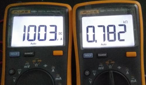
Left is input current of inverter and right is output impedance of CE
As shown in Fig. 4, current-limiting resistors at input and output of optocoupler are rated at 1kΩ, and input voltage is same, so input current of optocoupler can be obtained by adjusting voltage value of voltage regulator. Relationship between inverter and IC output current.
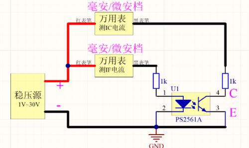
Figure 4: Experiment on relationship between input current IF and output current IC
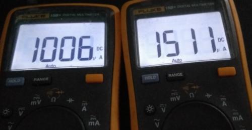
Input current IF is on left and output current IC is on right
As shown in experimental data obtained in Figure 5, trend of IC output current curve and IF input current curve are basically same, and CE impedance changes linearly when it is less than 1k. and minimum resistance is greater than 100 ohms.
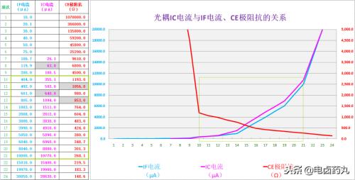
Figure 5. Experimental data
Therefore, when using a linear optocoupler to transmit switching signals, it is necessary to choose size of input impedance wisely. In Figure 1, input impedance is 360Ω, and forward voltage drop of optocoupler input is about 1V. The input current of IC is (5-1)/360≈11mA, output impedance of optocoupler CE is more than 200Ω , and coil resistance of HFD2 relay is 2880 ohms. At this time, relay can be controlled normally. If current of IC becomes smaller, impedance of CE becomes larger, which will cause it to fail to drive relay normally.
Linear optocoupler is mainly used to transmit analog signals, and output signal is equivalent to a variable resistor. Switching power supplies very often use an optocoupler as feedback to isolate high and low voltage. Commonly used are PC817, PS2561, PS2801. As in previous example, is also commonly used for toggle signals.
In fig. 7 shows a linear optocoupler inside switching power supply shown in fig. 6. The output voltage of switching power supply is isolated by a linear optocoupler and fed back to control chip to adjust output voltage in real time.
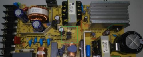
Figure 6: Application of an optocoupler in a switching power supply
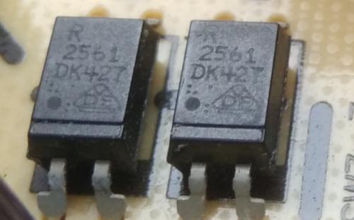
Figure 7: Optocoupler inside a switching power supply
Nonlinear optocouplers are mainly used to transmit switching signals (or digital signals). Commonly used 4N series include 4N25, 4N26 and TIL117; There are also high-speed optocouplers, such as 6N136 and 6H137, PS9714, PS9715, etc. It is mainly used for communication isolation and PWM wave control (which can effectively reduce electromagnetic interference). To judge whether it is a high-speed optocoupler, please see whether technical description indicates high speed (1 Mbps, 10 Mbps).
Highlights
①The main application of an optocoupler is isolation;
②When input impedance of linear optocoupler is same as output impedance at same voltage, output current of IC is basically same as input current of IF; even if input and output voltages are different, this can be realized by matching output and input resistance;
③ Both a linear optocoupler and a non-linear optocoupler can be used for signal switching, and linear optocoupler circuit cannot be replaced by a non-linear optocoupler;
④The response speed of non-linear optocoupler is faster than that of linear optocoupler, similar to response speed of comparator than operational amplifier.
Related
- Optocoupler and application circuit
- What is difference between surge device, lightning arrester, leakage protection, circuit breaker and circuit breaker? Come and get knowledge
- Experience in recognition of circuit diagrams of electronic circuits and method of circuit analysis
- Common USB Interface Circuit Design Problems and Solutions
- Diode switching circuit and troubleshooting, one complete wizard
- Explain in detail difference and application of two-three-four-wire system.
- Why are there always two capacitors in circuit 0.1uF and 0.01uF?
- Why always put two 0.1uF and 0.01uF capacitors in the circuit?
- You must learn drawing techniques and skills of 18 special circuit board routes.
- MOS tube drive circuit, how to make MOS tube turn on and off quickly?
Hot Posts
 How to distinguish induction from leakage, we will teach you three tricks! Ordinary people can also learn super practical
- What is drowning in gold? Why Shen Jin?
- This is a metaphor for EMI/EMS/EMC that can be understood at a glance.
- How many types of pads have you seen in PCB design?
- Summary of Common PCB Repair Techniques
- What is three anti-paint? How to use it correctly?
- Knowing these rules, you will not get confused looking at circuit diagram.
- How to make anti-interference PCB design?
- Can diodes do this?