Location:Home Page > Archive Archive
Why PCB design usually controls 50 ohm impedance
2023-03-18【Archive】
In PCB design process, we usually layer elements we want to design before wiring and calculate impedance based on thickness, base material, number of layers, and other information. After calculation, we can generally get following picture display content.
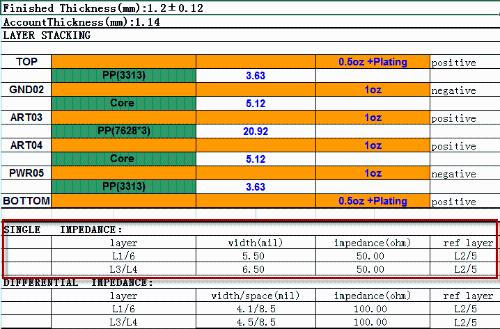
Fig. 1. Overlay Information Chart
As you can see from picture above, above single-ended network is typically driven with 50 ohms, so many people will ask why 50 ohms is required and not 25 ohms or 80 ohms?
First of all, default is 50 ohms, and everyone in industry accepts this value. Generally speaking, a specific standard must be formulated by a recognized organization and everyone is designed in accordance with standard.
Most electronic technology comes from military. First of all, technologies are used for military purposes, and then gradually move from military use to civilian use.
In early days of microwave applications, during World War II, choice of impedance was completely dependent on needs of application, and there was no standard value. As technology advances, impedance standards need to be specified to strike a balance between economy and convenience.
In United States, most commonly used conduits are connected with existing rods and water pipes. 51.5 ohms are very common, but adapters and converters seen and used are 50-51.5 ohms. In order to solve these problems for Navy, an organization called JAN (later DESC organization) was created, which was specially developed by MIL. After a comprehensive review, 50 ohms were finally selected and appropriate catheters were made, which thus developed into various standards for cables.
At that time, European standard was 60 ohms. Soon after, under influence of companies such as Hewlett-Packard who dominated industry, Europeans were also forced to change, so 50 ohms eventually became industry standard. , It has become a tradition, and circuit board connected to various cables to match impedance is finally required in accordance with 50 ohm impedance standard.
Secondly, development of common standards will be based on a comprehensive consideration of PCB manufacturing process, design characteristics and feasibility.
From point of view of PCB production and processing technology, given equipment of most existing PCB manufacturers, it is relatively easy to produce printed circuit boards with an impedance of 50 ohms.
It can be seen from impedance calculation process that too low impedance requires wider line width and thin dielectric or larger dielectric constant, which is difficult to satisfy current high-density board in terms of space; too high impedance requires a large thin line width, and a thick dielectric or small dielectric constant does not contribute to suppression of electromagnetic interference and crosstalk. At same time, processing reliability for multilayer boards and from point of view of mass production will be relatively poor.
U50 ohm impedance control With conventional boards (FR4, etc.) and ordinary core boards, it is possible to manufacture products with commonly used board thickness (for example, 1mm, 1.2mm, etc.) and create lines of standard width (4~10mil), so that carton factory is very convenient to process, and processing equipment requirements are not very high.
In terms of PCB design, 50 ohms was also chosen after extensive consideration. In terms of PCB trace performance, low impedance is generally better. For a transmission line with a given line width, closer distance to plane, smaller corresponding electromagnetic interference, and also crosstalk is reduced.
However, in terms of entire signal path, most important factor to consider is bandwidth of chip. In early days, most chips could not drive transmission lines with an impedance of less than 50 ohms. Ohm, and transmission lines with a higher one are inconvenient to get up, so a compromise resistance of 50 Ohm is used.
Therefore, 50 Ω is typically selected as default value for single-ended driving impedance during normal operation.
Related
- Why PCB design usually controls 50 ohm impedance
- Switching Power Supply PCB Design Skills
- How to make anti-interference PCB design?
- PCB design guidelines: safety regulations, layout and wiring, EMC, thermal design, process engineering.
- With these two schematics, PCB design is easy!
- A Few Design Tips PCB Engineers Need to Know
- How many types of pads have you seen in PCB design?
- Why can't crystal oscillator be placed on edge of the PCB?
- Do you know layout requirements of some special devices in PCB design?
- Case analysis! Why can't crystal oscillator be placed on edge of PCB?
Hot Posts
 How to distinguish induction from leakage, we will teach you three tricks! Ordinary people can also learn super practical
- What is drowning in gold? Why Shen Jin?
- This is a metaphor for EMI/EMS/EMC that can be understood at a glance.
- How many types of pads have you seen in PCB design?
- Summary of Common PCB Repair Techniques
- What is three anti-paint? How to use it correctly?
- Knowing these rules, you will not get confused looking at circuit diagram.
- How to make anti-interference PCB design?
- Can diodes do this?