Location:Home Page > Archive Archive
Why always put two 0.1uF and 0.01uF capacitors in the circuit?
2023-03-18【Archive】
01 Travel and Split
The two concepts of Bypass Capacitor and Decoupling Capacitor are common in circuits, but not easy to understand.
To understand these two words, we need to go back to English context.
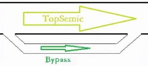
Bypass means driving on a small road in English, and also means it on a ring road, as shown in picture below.
Pair means pair in English, and this extended meaning means connection and connection. If a signal in system A causes a signal in system B, then it is said that there is a coupling phenomenon between system A and system B, as shown in figure below. And decoupling means to loosen that bond.
02 Bypassing and decoupling
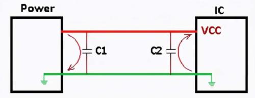
As shown in figure below, DC power supply supplies power to IC chip, and two capacitors are included in circuit.
1) Bypass
If power fails, it is usually a relatively high frequency interference signal that can cause IC to malfunction.
Connect capacitor C1 in parallel near power supply because capacitor is open to DC and has low resistance to AC.
The RFI signal returns to ground via C1, and RFI signal that would have passed through IC flows to GND via a short circuit through capacitor. C1 is function of shunt capacitor.
2) Separation
Because operating frequency of integrated circuits is generally relatively high, large current fluctuations will be generated in power wires when IC starts up or when operating frequency is switched. The ability to cause vibrations.
Connect capacitor C2 in parallel with VCC power supply port near IC. Because capacitor has a power storage function, it can provide instantaneous current for IC and reduce effect of IC current fluctuations on power. C2 acts as a decoupling capacitor here.
03 Why use 2 capacitors
Returning to question mentioned at beginning of this article: Why use two 0.1uF and 0.01uF capacitors?
The formulas for calculating capacitive impedance and capacitive reactance are as follows:
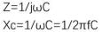
The capacitance is inversely proportional to frequency and capacitance value. The larger capacitance and higher frequency, lower capacitance. One can simply understand that larger capacitance, better filtering effect.
Thenwouldn't it be a waste of time to add a 0.01uF capacitor to 0.1uF shunt capacitor?
Actually, for a particular capacitor, it is capacitive when frequency of signal is below its own resonant frequency, and inductive when frequency of signal is above its own resonant frequency.
If two 0.1uF and 0.01uF capacitors are connected in parallel, this is equivalent to extending filter's bandwidth.
Related
- Why always put two 0.1uF and 0.01uF capacitors in the circuit?
- Why are there always two capacitors in circuit 0.1uF and 0.01uF?
- The role of polar and non-polar capacitors in parallel connection
- Experience in recognition of circuit diagrams of electronic circuits and method of circuit analysis
- Why doesn't a push-pull gate type circuit use a top P and a bottom N?
- Why is capacitance Y generally not more than 0.1uF?
- Explain in detail difference and application of two-three-four-wire system.
- Inventory of 27 functions of capacitors in circuits
- Optocoupler and application circuit
- What is difference between surge device, lightning arrester, leakage protection, circuit breaker and circuit breaker? Come and get knowledge
Hot Posts
 How to distinguish induction from leakage, we will teach you three tricks! Ordinary people can also learn super practical
- What is drowning in gold? Why Shen Jin?
- This is a metaphor for EMI/EMS/EMC that can be understood at a glance.
- How many types of pads have you seen in PCB design?
- Summary of Common PCB Repair Techniques
- What is three anti-paint? How to use it correctly?
- Knowing these rules, you will not get confused looking at circuit diagram.
- How to make anti-interference PCB design?
- Can diodes do this?