Location:Home Page > Archive Archive
Experience in recognition of circuit diagrams of electronic circuits and method of circuit analysis
2023-03-18【Archive】
Electronic circuit diagrams, as a rule, consist of circuit diagrams, block diagrams and assembly (installation) diagrams. The circuit diagram is an important part of electronic circuit diagram. It consists of various symbols (graphic, text) and consists of commenting characters.
From circuit diagram, we can see specific parameters (such as model, rating) of each electronic component and connection relationship between each component.
Understanding images is a basic skill for electronics technicians. Through reading pictures, people can become familiar with structure and working principle of equipment as soon as possible, and understand connection and installation of various components and tools. production or service; card recognition also helps us quickly familiarize ourselves with various new electronic devices and equipment.
1 How to recognize circuit diagrams of electronic circuits
To read circuit diagrams of electronic circuits, it is necessary to understand and master certain basic knowledge in field of electronic technology.
However, due to years of experience teaching electronic technology, I think there are certain methods to follow when reading electronic circuit schematic diagrams. Let me share some combinations of lighting control and voice control with lighting delay in corridors (Fig. 1). Summarize.

1. Parse circuit into blocks and divide into several single circuits
Some complex circuits can usually be divided into several parts according to functions implemented by circuit. In this way, a complex circuit can be decomposed into several simple circuits for analysis, which simplifies difficulty of circuit analysis.
For example, a lighting circuit with a light and sound control delay can be divided into four parts: a sound control receive amplifier circuit, a monostable delay circuit, a light control circuit, and a power circuit. The dividing line of each part is shown in Figure 1 (Note: C2 refers to power circuit part).
Another example is that an AM radio circuit can be decomposed into several separate circuits such as input loop, frequency mixing, midrange amplifier, bass preamplifier and power amplifier.
2. Learn structure and characteristics of typical block diagrams
Common typical block circuits include amplifier circuits, oscillator circuits, filter circuits, etc. These unit circuits usually consist of triodes or integrated circuits as main devices and have a certain structural form. Some complex circuits are formed by expanding these typical single schemes.
For example, an amplifier circuit is usually a single circuit with a triode or integrated operational amplifier as core, and its design feature is that it has an input and output terminals; oscillatory circuit is usually a single circuit. with a triode or built-in operational amplifier as core.
Its design feature is that there is no external circuit input terminal, and a positive feedback network with a frequency selection function is connected between input terminal and output terminal of triode or integrated operational amplifier; The filter circuit usually adopts built-in operational amplifier as core. A feature of its design is that it contains a capacitor or an inductor, and a feedback element is connected between the output and input terminals.
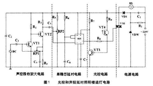
In Figure 1, audio control receiving amplifier circuit is a block diagram with triodes VT1 and VT2 as core, and lighting control circuit is a block diagram with VT3 as core.
For another example, flip-flop circuit uses basic RS flip-flop as a memory block circuit to form basic logic unit of other complex flip-flops, such as synchronous RS flip-flop, which is based on basic RS flip-flop and adds two more NOT gates.
The master-slave RS flip-flop consists of two synchronous RS flip-flops, and JK master-slave flip-flop is formed by adding two AND gates based on RS master-slave flip-flop.
You can see that Synchronous RS flip-flops, Master-slave RS flip-flops, and Master-slave JK flip-flops are incrementally expanded based on basic RS flip-flops. basic logic that makes up these complex trigger blocks, mastering it will lay foundation for us to study following types of triggers.
3. Understanding Characteristics of Power Circuits
Electronic circuits typically use a regulated DC power supply as power source to supply power to circuit. A regulated DC power supply usually consists of four parts: conversion, rectification, filtering, and voltage regulation. Through these four parts of circuit, AC power is converted into DC.

As shown in Figure 1, 220V AC voltage is stepped down by capacitors C1 and R1, clipped by diode VDW, and rectified by voltage VD1, and resulting DC voltage is filtered by capacitor C2 to provide operating voltage for entire circuit.
Another example is some doorbell circuits, charging circuits, and switching circuits. When energizing these circuits, 220V network is typically stepped down by a transformer, rectified by a four-diode rectifier bridge, filtered by a capacitor, and stabilized by a voltage regulator tube. These steps convert AC to DC to provide stable power to circuit.
4. Classify circuits and learn circuits by category
Electronic circuits can generally be divided into following general categories: alarm circuit, doorbell circuit, oscillation circuit, power circuit, lighting and lantern control circuit, switch and detection circuit, sensor application circuit, 555 timer application circuit, etc.
Although above types of circuits use different electronic components, functions implemented by circuits are basically same, so circuit can be analyzed starting from functions implemented by circuit.
In addition, knowing typical circuit structure and characteristics of some devices will also make it easier for us to analyze some complex circuits.
For example, a typical 555 timer circuit mainly includes a monostable flip-flop, a multivibrator, and a bistable flip-flop composed of a 555 timer. circuits, timers, etc.
A multivibrator consisting of 555 could be a clock generator, etc., and a flip-flop consisting of 555 could be a logic level test circuit, etc.
As shown in Figure 1, corridor lighting delay function is implemented by a monostable trigger consisting of a 555 timer.
5. Explore a specific type of trail from shallow to deep
For example, for doorbell circuit, we can first understand principle of simple doorbell circuit, and then continue to study principle of simple transposition doorbell circuit and double tone doorbell circuit, because last two types of doorbell circuits are improved on basis of a simple doorbell circuit formed by expansion.

As shown in figure 1, this is lighting and sound control delay switch circuit. We can start with a relatively simple lighting control switch circuit, and then study lighting control delay switch circuit on that basis, and finally study lighting control delay switch circuit. Double sound and light. It is relatively easy to control delay switch circuit.
Related
- Experience in recognition of circuit diagrams of electronic circuits and method of circuit analysis
- Circuit Analysis of 6 Examples Explaining Lightning Surge Protection in Detail
- Principal analysis of BUCK / BOOST circuit, a summary is also in place
- Analysis of power circuit of a classic single-chip microcomputer
- Analysis of damping RC circuit of a switching power supply "haberdashery"
- Haberdashery|General failure mechanism and analysis of electronic components
- What does inside of a multilayer PCB look like? Three-dimensional general analysis of design process of high-quality printed circuit boards
- In circuit design, what are differences between six types of grounds?
- Analysis and comparison of 6 most commonly used DC power supply circuits
- You must learn drawing techniques and skills of 18 special circuit board routes.
Hot Posts
 How to distinguish induction from leakage, we will teach you three tricks! Ordinary people can also learn super practical
- What is drowning in gold? Why Shen Jin?
- This is a metaphor for EMI/EMS/EMC that can be understood at a glance.
- How many types of pads have you seen in PCB design?
- Summary of Common PCB Repair Techniques
- What is three anti-paint? How to use it correctly?
- Knowing these rules, you will not get confused looking at circuit diagram.
- How to make anti-interference PCB design?
- Can diodes do this?