Location:Home Page > Archive Archive
Circuit Analysis of 6 Examples Explaining Lightning Surge Protection in Detail
2023-04-28【Archive】
1. Lightning surge test standard for electronic equipment
The national standard for lightning surge testing of electronic equipment is GB/T17626.5 (equivalent to international standard IEC61000-4-5).
The standard is mainly intended to simulate various situations caused by indirect lightning strikes:
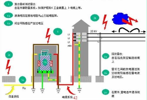
(1) When lightning strikes an external line, a large current flows into external line or ground resistance, which generates interference voltage.
(2) Indirect lightning strikes (eg, lightning strikes between or within clouds) induce voltage and current in external lines.
(3) Lightning strikes objects adjacent to line, and a strong electromagnetic field is established around it, which induces voltage on external line.
(4) Interference caused when lightning strikes a neighboring earth and current through earth passes through public earthing system.
In addition to simulating lightning strikes, standard also simulates disturbances that occur during switching in substations and other cases (voltage transients caused by switching switches), for example:
(1) Noise generated when main power system is switched (for example, when capacitor banks are switched).
(2) The same mains, interference when some small switches next to equipment jump.
(3) Switch thyristor devices with resonant lines.
(4) Various systemic faults such as short circuits and arcing between equipment earth networks or earth systems.
The standard describes two different signal generators: one is signal induced by a lightning strike on power line, and other is signal induced by communication line.
These two lines are all air lines, but their impedances are different: shape of pulse induced on power line is narrower (50 µS) and leading edge is steeper (1.2 µS). The ejection wave generated by online induction is wider, but leading edge is slower. In following, we will mainly analyze circuit based on waveform caused by a lightning strike on a power line, and also briefly introduce lightning protection technology of a communication line.
2. The principle of operation of simulated circuit for generating a lightning surge impulse
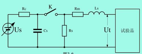
The figure above shows a circuit for generating pulses to simulate overvoltage that occurs in a power line when lightning strikes power distribution equipment, or anti-high voltage generated by lightning current passing through common ground resistance after a lightning strike. . The energy of a single pulse at a voltage of 4 kV is 100 J.
In figure, Cs is a capacitor for energy storage (about 10 uF, which is equivalent to a thundercloud capacitor); Us is high voltage power supply; Rc is charging resistance; Rs is resistance that forms pulse duration (the resistance that forms discharge curve). ; Rm corresponds to impedance The resistance Ls forms an inductance for current to rise.
Lightning surge test parameters have different requirements for different products. The parameters in above figure may be slightly modified according to different standard product requirements.
Basic parameter requirements:
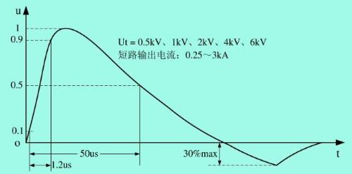
(1) Open-circuit output voltage: 0.5-6kV, divided into 5 output voltage levels, last level is determined by user and manufacturer through negotiation;
(2) Output short circuit current: 0.25~2kA, for different test levels;
(3) Internal resistance: 2 ohms, additional resistance 10, 12, 40, 42 ohms, for other tests of different levels;
(4) Pulse output polarity: positive/negative; when pulse output is synchronized with power supply, phase shift is 0~360 degrees;
(5) Repeat frequency: at least once per minute.
The severity level of lightning surge test is divided into 5 levels:
Level 1: well protected environment;
Level 2: Environment with some protection;
Level 3: normal environment with electromagnetic interference, no special requirements for installation of equipment, such as industrial workplaces;
Tier 4: Environments subject to severe disturbance, such as civilian overhead lines and unprotected high voltage substations.
Level X: determined by negotiation between user and manufacturer.
The 18uF capacitor in picture can be chosen according to degree of severity, and selected value can also be different, but after a certain value, it basically does not make much sense.
The 10 ohm resistor and 9 uF capacitor can be selected according to level of severity, and selected values also differ. The minimum value of resistor can be 0 ohm (this is case in American standard), and 9 uF capacitor can also be chosen very large, but it is large enough up to a certain value. After that it doesn't really make much sense.
3. Common mode surge suppression circuit
When designing anti-surge protection, it is assumed that two parts of common mode and differential mode are independent of each other. However, two parts are not really independent because common mode chokes can provide significant differential inductance. This part of differential mode inductance can be modeled using discrete differential mode inductors.
In order to use differential mode inductance, common mode and differential mode must not be performed at same time during design process, but must be performed in a specific order. First, common mode noise must be measured and filtered out. By using a differential mode suppression network, differential mode components can be eliminated so that common mode noise can be directly measured.
If common mode filter is designed so that differential noise does not exceed allowable range, then mixed common mode and differential mode noise should be measured. Since common mode component is known to be below acceptable noise level, only differential component is exceeded, which can be attenuated by differential leakage inductance of common mode filter. For low power power systems, differential mode common mode choke inductance is sufficient to solve differential mode radiation problem because differential mode radiation source impedance is small, so only a very small amount of inductance is effective.
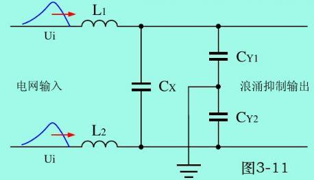
In order to suppress surges below 4000 Vpk, it is generally necessary to use only an LC circuit for current limiting and smoothing filtering, and also try to reduce pulse signal to a level 2-3 times average value of pulse signal. The inductance saturates easily, so L1 and L2 usually use common mode inductance with large leakage inductance.
Used on both AC and DC, we typically see it in power EMI filters and switching power supplies, but rarely on DC side, and can be seen on DC side of automotive electronics. The purpose of adding common mode chokes is to eliminate common mode noise on parallel lines (two-wire and multi-wire). Due to unbalanced impedance of two wires in circuit, common mode noise is eventually reflected in differential mode. Difficult to filter by differential filtering. Where should a common mode inductor be used? Common mode interference is usually spatially coupled electromagnetic radiation, so whether it is AC or DC, if you have a long term transmission it involves common mode filtering and you must add a common mode inductor. For example: if there are many USB cables, add a magnetic ring to cable. Switching power supply input, AC power needs to be added if it is transmitted over a long distance. Normally, DC side does not need remote transmission and does not need to be added. There is no common mode noise, adding it is a waste of time, and there is no amplification in circuit.
The design of a power filter can usually be considered in terms of two aspects: common mode and differential mode. The most important part of common mode filter is common mode choke. Compared with differential choke, significant advantage of common mode choke is that its inductance value is extremely large and volume is small. Common mode choke design An important issue to consider when using a flow coil is its leakage inductance, which is differential mode inductance. Generally, way to calculate leakage inductance is to assume that it is 1% of common mode inductance, in fact leakage inductance is between 0.5% and 4% of common mode inductance. The influence of this error cannot be neglected when designing a choke for optimum performance.
Importance of leakage inductance
How is leakage inductance formed? A tightly wound toroidal coil with one full turn, even without a magnetic core, all of its magnetic flux is concentrated in "core" of coil. However, if toroid is not wound one full turn, or if it is not wound tightly, flux will flow out of core.ka. This effect is proportional to relative spacing between turns and magnetic permeability of coiled tube core.
A common mode choke coil has two windings that are designed so that currents flowing through them are conducted in opposite directions along coil core so that magnetic field is zero. If, for safety reasons, coils on core are not wound bifilarly, then there is a significant gap between two windings, which naturally causes "leakage" of flux, i.e. magnetic field at various points of interest is not really 0. The leakage inductance of a common mode choke is a differential mode inductance. In fact, flux associated with differential mode must leave core at some point, in other words, flux forms a closed loop outside core, not just inside toroidal core.
Typically, CX capacitors can withstand 4000 Vpk of differential mode overvoltage and CY capacitors can withstand 5000 Vpk of common mode voltage. Proper selection of parameters L1, L2, CX2 and CY can suppress common mode and differential overvoltages below 4000 Vpk. However, if two CY capacitors are installed in circuit of whole machine, total capacitance cannot exceed 5000P. If overvoltage exceeds 4000V, a capacitor with a higher withstand voltage and overvoltage suppression with a circuit limiting function should be selected.
So-called suppression simply reduces amplitude of peak pulse and then converts it into a different waveform output signal with a relatively wide pulse width and relatively flat amplitude, but its energy is largely unchanged.
The capacitance of two capacitors CY is generally very small, stored energy is limited, and their influence on common mode suppression is not very large. Therefore, common mode overvoltage suppression mainly depends on inductors L1 and L2, but due to L1, inductance of L2 is also limited by volume and cost, and is generally difficult to make very large, so above circuit has limited effect on suppressing common-mode lightning surges.
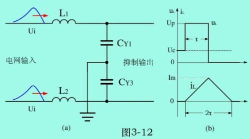
In figure (a), L1 and CY1, L2 and CY2 suppress two common mode overvoltages respectively, and only one of them needs to be calculated during calculation. ØTo accurately calculate L1, it is necessary to solve a system of second-order differential equations. The results show that: charge of capacitor is carried out along a sinusoid, and discharge - along a cosine wave. However, this calculation method is more complex and a simpler method is used here.
The common mode signal is a square wave with amplitude Up and width τ, and voltage across capacitor CY is Uc, and measured current flowing through inductor is a sawtooth wave with a width equal to 2τ :
Current through an inductor:
Maximum current flowing through inductor:
The average current flowing through inductor for 2τ is:

From this you can get change in voltage of capacitor CY for 2τ as:
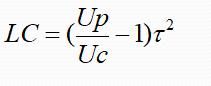
The above formula is calculation formula for calculating parameters of inductor L and capacitor CY in common mode surge suppression circuit. In formula, Uc is voltage at both ends of capacitor CY, which is also output voltage of surge suppression circuit ∆Uc is two However, since period of lightning impulse is very long and duty cycle is very short, it can be considered that Uc = ∆Uc, Up is peak value of total overvoltage impulse, q is charge stored in capacitor CY, τ is common mode overvoltage impulse. Overvoltage pulse width, L - inductance, C - capacitance.
According to above formula, assuming peak surge voltage Up=4000Vp, capacitance C=2500p, and output voltage Uc=2000Vp of surge suppression circuit, value of inductance L is 1H. Obviously, this value is very large and difficult to implement in practice, so above circuit has limited ability to suppress common-mode lightning discharges, and this circuit needs to be further improved.
The overvoltage suppression in differential mode mainly depends on choice of filter inductors L1, L2 and filter capacitor CX in figure.
However, L in above formula should be equal to sum of two filter inductors L1 and L2, C=CX, and Uc equal to differential mode suppression output voltage. As a general rule, output voltage with differential mode suppression should not exceed 600 Vpk, since maximum withstand voltage of many semiconductor devices and capacitors is approximately equal to this voltage, and after filtering by two filter inductors L1 and L2 and a capacitor CX, lightning discharge differential discharge impulse mode voltage Although amplitude decreases, energy basically does not decrease, because after filtering, pulse width will increase. After device fails, most of it cannot be restored to its original state.
According to above formula, assuming peak surge voltage Up=4000Vpeak, pulse width is 50µS, and output voltage Uc=600Vpeak of differential mode surge suppression circuit, LC value should be 14mH×µF. Obviously, this value is still relatively large for surge suppression circuit in conventional electronic products. On contrary, increasing inductance is more beneficial than increasing capacitance, so it is better to choose a 3-window silicon steel circuit. as an iron core, and an inductor with a relatively large inductance (more than 20mH) is used as a pulse inductor. This type of inductor has a large common-mode and differential inductance, and is not easy to saturate. Incidentally, electrolytic filter capacitor behind rectifier circuit also has a surge suppression function. If thisand function is enabled, output voltage Uc cannot be selected as 600Vp, but can only be selected as maximum withstand voltage Ur capacitor (400Vp).
4. General Lightning Surge Suppression Devices
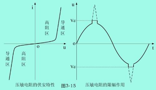
Lightning protection devices mainly include ceramic gas discharge tubes, zinc oxide varistors, thyristors (TVS), surge suppression inductors, X-type surge suppression capacitors, etc. Various devices should be used in combination.
There are many types of gas discharge tubes, discharge current is generally large, up to tens of kA, and discharge voltage is relatively large. The discharge tube needs a certain time to discharge from ignition to discharge, and there is a residual voltage, so performance is not stable, oxidationVolt-ampere characteristics of zinc varistors are relatively good, but due to power limitation, current is relatively smaller than that of gas discharge tubes. After repeated breakdown of lightning overcurrent, breakdown voltage value will drop or even fail;
TVS semiconductor tube has best volt-ampere characteristics, but power is generally very small and cost is relatively high; The surge suppression coil is most basic lightning protection device. To prevent saturation of alternating current flowing through power grid, a three-window iron core must be selected; a capacitor X is also needed, and a capacitor with a large ripple current rating must be selected.
Discharge tube
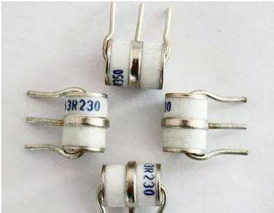
The discharge tube is a type of lightning arrester or antenna switch tube for surge protection. The tube has two or more electrodes and is filled with a certain amount of inert gas. The discharge tube is a slot-type lightning protection component that is used in lightning protection of a communication system.
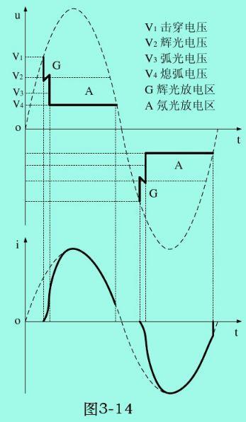
The principle of operation of a gas discharge tube is a discharge in a gas gap. When a certain voltage is applied between two poles of discharge tube, an uneven electric field will be created between electrodes: under influence of this electric field, gas in tube will begin to dissociate When applied voltage increases to When field strength between poles exceed gas insulation strength, gap between two poles will destroy discharge, and original insulating state will be converted to a conductive state. The residual voltage level, which is usually very low, so that electronic equipment connected in parallel with discharge tube will not be damaged by overvoltage.
Some gas discharge tubes use glass as outer shell of tube. Some also use ceramics as body shell, and discharge tube is filled with an inert gas with stable electrical properties (such as argon, neon gas, etc.) The discharge electrodes of commonly used discharge tube are usually two or three, electrodes are separated by an inert gas. Depending on setting of number of electrodes, gas discharge tubes can be divided into two-pole and three-pole gas discharge tubes.
The ceramic diode discharge tube is composed of a pure iron electrode, a nickel-chromium-cobalt alloy cap, a silver-copper welding cap, and a ceramic tube body. The discharge electrodes in tube are coated with radioactive oxides, and inner wall of tube is also coated with radioactive elements to improve discharge characteristics.
The discharge electrode mainly has two structures: rod and bowl. In discharge tube of rod electrode, a cylindrical heat shield is installed between electrode and wall of tube body. The heating tends to be uniform, and tube will not burst due to local overheating. The inside of heat shield is also coated with radioactive oxides to further reduce discharge dissipation. A molybdenum mesh is installed in discharge tube of cup-shaped electrode at mouth of glass, and a cesium element is installed in glass, which also reduces dissipation of discharge.
The three-electrode discharge tube also consists of pure iron electrodes, nickel-chromium-cobalt alloy caps, silver-copper welding caps, and ceramic tubes. Unlike diode discharge tube, a nickel-chromium-cobalt alloy cylinder is added to three-electrode discharge tube as third pole, that is, ground electrode.
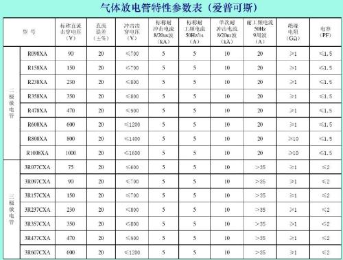
Main parameters:
(1) DC breakdown voltage. This value is determined by applying a voltage at a low slew rate (dv/dt=100 V/s).
(2) Impulse (or impulse) breakdown voltage. It represents dynamic characteristics of discharge tube and is usually determined by voltage value, rate of rise of which is dv/dt=1 kV/µs.
(3) Rated impulse discharge current. Nominal waveform discharge current 8/20 µs (rising edge 8 µs, half-peak duration 20 µs), typically discharge 10 times.
(4) Standard discharge current. In accordance with rated effective value of alternating current with a frequency of 50 Hz, it is provided that time of each discharge is 1 s, and discharge time is 10 times.
(5) Maximum single pulse discharge current. Single maximum discharge current for current wave 8/20 µs.
(6) Power frequency current resistance value. Single maximum discharge current for current wave 8/20 µs. For 50 Hz alternating current, effective value of maximum current that can withstand 9 consecutive cycles.
(7) Insulation resistance. Single maximum discharge current for current wave 8/20 µs. For 50 Hz alternating current, effective value of maximum current that can withstand 9 consecutive cycles.
(8) Capacity. The capacitance between discharge tube electrodes is typically 2 to 10 pF, which is smallest value of any crosstalk absorbing device.
Metal oxide varistor
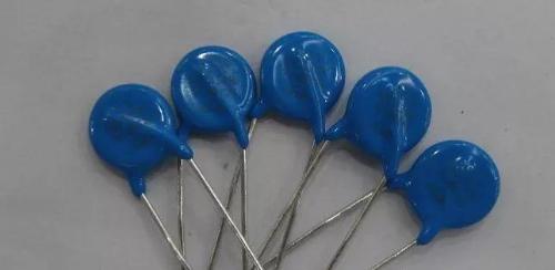
Varistors are usually made with zinc oxide as main component, as well as a small amount of other metal oxides (particles) such as pressed cobalt, manganese, bismuth, etc. Since two objects with different properties are combined together, it is equivalent to PN -transition (diode), therefore, varistor is equivalent to a set of PN junctions connected in series and in parallel.
5. Surge suppression circuit
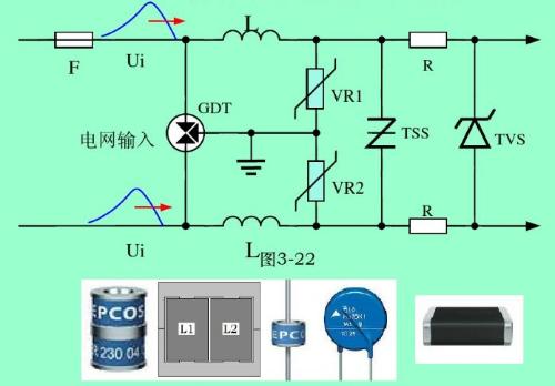
Example 1
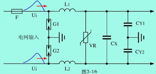
The above figure shows an electrical circuit diagram that can withstand strong surge voltage of a lightning discharge. In figure: G1 and G2 are gas discharge tubes, which are mainly used to suppress high-voltage common-mode pulses and for high-voltage surge differential voltage The pulse also has ability to suppress, VR is a piezoresistor, which is mainly used to suppress overvoltage pulse in high voltage differential mode. After suppression of G1, G2 and VR, amplitude and energy of common-mode and differential overvoltage pulses are significantly reduced.
The breakdown voltage of G1 and G2 can be selected from 1000 to 3000 Vpk, and varistor voltage VR is typically 1.7 times maximum power frequency voltage.
After breakdown of G1 and G2, additional current will be generated. A fuse must be added to prevent too high additional current and a short circuit in line.
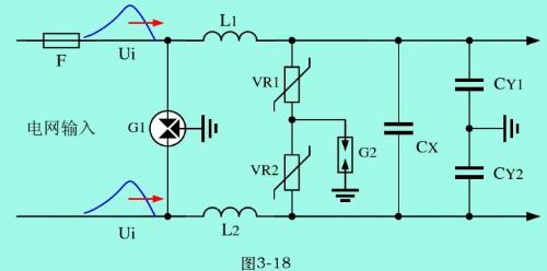
Example 2
Two varistors VR1, VR2 and gas discharge tube G3 have been added. The main purpose is to strengthen suppression of common mode surges, since varistors have leakage current, and ordinary electronic products have very high leakage current requirements Strict (less than 0.7mA), so G3 discharge tube is added in figure to make circuit leakage current at ground to 0. G3 breakdown voltage is much smaller than G1 and G2 breakdown voltage. mode Strong braking effect.
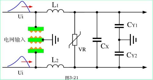
Example 3
G1 is a three-terminal discharge tube, which is equivalent to installing two two-terminal discharge tubes in one package, and can replace G1 and G2 discharge tubes in above two examples. In addition to two- and three-terminal discharge tubes, there are also four-terminal and five-terminal discharge tubes, and use of each discharge tube is not exactly same.
Example 4
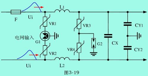
Add two piezoresistors (VR1, VR2), main purpose is to cut off follow current generated after breakdown of G1 in case follow current is too large to short circuit input circuit, but maximum peak current of VR1 and VR2 is usually only a few tenths of G1, so ability of this example to suppress ultra-high overvoltages is much worse than that of example 3.
Example 5. Manufacturing a lightning protection device directly on a printed circuit board
Directly make a lightning protection device on PCB, which can replace lightning protection discharge tube, and can suppress effect of tens of thousands of volts of common mode or differential overvoltage. When distance between electrodes is 4.5mm, when input voltage is AC 220V, distance between electrodes can be 6mm; middle electrode of lightning protection device must be connected to port where three-pin power line is connected to printed circuit board.
Example 6: PCB air gap discharge device instead of gas discharge tube
Install air-gap discharge device directly on circuit board, normal discharge voltage is 1000-1500V/mm, discharge voltage at 4.5mm creepage distance is about 4500-6800Vpk, and discharge voltage at 6mm creepage distance is about 6000 V. ~9000Vp.
6. Connecting various lightning protection devices
The installation order of lightning protection devices cannot be wrong. The discharge tube should be in front, followed by surge suppression choke and varistor (or discharge tube), and then TVS semiconductor thyristor or X-type capacitor and Y class capacitor.
Related
- Circuit Analysis of 6 Examples Explaining Lightning Surge Protection in Detail
- What is difference between surge device, lightning arrester, leakage protection, circuit breaker and circuit breaker? Come and get knowledge
- Power port lightning protection circuit
- Experience in recognition of circuit diagrams of electronic circuits and method of circuit analysis
- Principal analysis of BUCK / BOOST circuit, a summary is also in place
- Analysis of power circuit of a classic single-chip microcomputer
- Analysis of damping RC circuit of a switching power supply "haberdashery"
- Detailed analysis of the "various protection schemes" of a switching power supply
- Explain in detail classification of more than a dozen types of "recommended collection" capacitors
- What does inside of a multilayer PCB look like? Three-dimensional general analysis of design process of high-quality printed circuit boards
Hot Posts
 How to distinguish induction from leakage, we will teach you three tricks! Ordinary people can also learn super practical
- What is drowning in gold? Why Shen Jin?
- This is a metaphor for EMI/EMS/EMC that can be understood at a glance.
- How many types of pads have you seen in PCB design?
- Summary of Common PCB Repair Techniques
- What is three anti-paint? How to use it correctly?
- Knowing these rules, you will not get confused looking at circuit diagram.
- How to make anti-interference PCB design?
- Can diodes do this?