Location:Home Page > Archive Archive
Three common grounding methods in circuit design
2023-03-26【Archive】
As we all know, good EMC circuitry goes hand in hand with excellent grounding. This article details three common grounding methods.
1. Land division and connection
Grounding is one of important means of suppressing electromagnetic interference and improving electromagnetic compatibility characteristics of electronic equipment. Proper grounding can not only improve product's ability to suppress electromagnetic interference, but also reduce external electromagnetic radiation of product.
Second, meaning of grounding
Equipment ground usually has two meanings, one is ground (safety ground) and other is system reference ground (signal ground). Grounding refers to creating a low-resistance conductive path between system and a defined potential reference plane. "Ground connection" means using ground potential as a reference and ground as ground potential to connect metal enclosure of electronic equipment and circuit reference point to ground. Connecting ground layer to earth is often associated with following considerations:
1. Improve stability of equipment chain system;
2. Static discharge;
3. Ensure safety of personnel.
Third, purpose of grounding
1. Safety considerations, namely protective earthing;
2. Provide a stable zero potential reference point (signal ground or system ground) for signal voltage;
3. Screen grounding.
Four, three common grounding methods
1. Grounding at one point
Single point grounding, as name suggests, is to connect all circuits in a circuit to same reference potential point.
Single-point grounding can be divided into two methods: "series grounding" and "parallel grounding". The serial single-point grounding method is simple, but there is a common ground wire, resulting in a common ground wire impedance. If circuits with a large power difference are connected in series at this time, mutual interference will be very serious. The parallel single-point grounding method avoids coupling factor of common ground wire, but each part of circuit must lead ground wire to ground point, and required ground wire is too large, which is impractical.
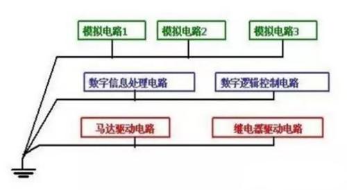
Thus, in practical applications, method of single-point grounding in series and parallel connection can be used. When drawing a PCB, place circuits that don't interfere with each other on same layer, circuits that easily interfere with each other on different layers, and then connect grounds of different layers in parallel. as shown below.
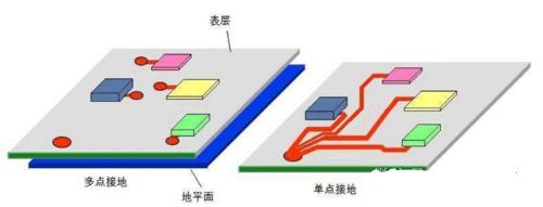
Single point grounding is not applicable in high frequency circuits because ground wire is long and ground wire impedance is an unavoidable factor. What should I do? "Multi-point grounding" will be presented below.
2. Multi-point grounding
When circuit operating frequency is high, imagine how high frequency signal will affect surrounding circuits when propagating along ground wire, so all circuits must be connected to ground nearby, and ground wire is required as short as possible, multi-point grounding is performed. The purpose of multi-point grounding is to reduce impedance of lightning wire. In high frequency (under certain f conditions) circuits, there are two main considerations to reduce impedance. One is to reduce resistance of lightning wire, and other is to reduce impedance of ground wire.
a. In order to reduce conductor resistance of lightning conductor, we know from formula for relationship between resistance and cross-section that cross-sectional area of the lightning conductor must be increased. However, in a high-frequency environment, a high-frequency current skin effect (also called skin effect) occurs and high-frequency current will flow through surface of conductor, so simply increasing cross-sectional area of the ground wire often has little effect. You can consider applying silver to surface of conductor because conductivity of silver is better than other conductive substances, so it will reduce resistance of conductor.
b. The best way to reduce inductive reactance of ground wire is to increase area of the ground wire. In actual application, ground wire is short and ground area is large, so anti-interference effect will be better.
While writing this, some people may ask, what is a high frequency circuit? "Typically, a low frequency circuit below 1 MHz can use a single point ground, and a high frequency circuit above 10 MHz can use a multi point ground." wavelength, single point grounding can be used Point grounding or multipoint grounding. As shown in picture:
3. Hybrid Playground
As shown in figure, analyze graph.
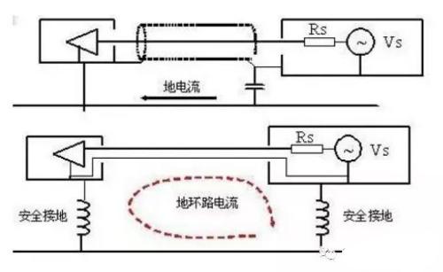
The first structure in above figure is assumed to operate in a low frequency circuit. According to capacitance Zc = 1/2πfc, it can be known that capacitance is large in low frequency environment and small in high frequency environment. The ground wire then cuts off at low frequencies and shorts to conduction when it is disturbed by high frequencies. This connection can effectively avoid ground loop interference.
It is assumed that second structure in above figure works in a high frequency circuit. According to inductive reactance Zl = 2πfl, it can be seen that inductive reactance is small in a low frequency environment, but large in a high frequency environment. Then ground wire is like conduction at low frequency, and it cuts out when it is disturbed by high frequency. Such a connection can effectively avoid influence of ground loop current.
Summarizing, in practical applications, circuit uses a suitable grounding method according to working environment, which can effectively avoid interference signals and achieve best circuit effect. Mixed grounding would be a good choice!
V. Resume
The general principles for choosing grounding are as follows:
1. For low frequency circuits (<1 MHz) a single point grounding is recommended;
2. For high frequency circuits (>10 MHz) it is recommended to use multi-point grounding;
3. Mixed circuit of high and low frequency, mixed grounding.
Related
- Three common grounding methods in circuit design
- Common USB Interface Circuit Design Problems and Solutions
- In circuit design, what are differences between six types of grounds?
- What does inside of a multilayer PCB look like? Three-dimensional general analysis of design process of high-quality printed circuit boards
- Industrial Computer Circuit Design
- Hardware Collection: 50 Common Circuit Diagrams
- Hardware Circuit Design Specification: A Very Good Reference to Hardware Design
- Senior engineer summarizes 10 methods for complex circuit analysis
- How to design a triode amplifier circuit
- Frequently Asked Questions for USB Interface Circuit Design
Hot Posts
 How to distinguish induction from leakage, we will teach you three tricks! Ordinary people can also learn super practical
- What is drowning in gold? Why Shen Jin?
- This is a metaphor for EMI/EMS/EMC that can be understood at a glance.
- How many types of pads have you seen in PCB design?
- Summary of Common PCB Repair Techniques
- What is three anti-paint? How to use it correctly?
- Knowing these rules, you will not get confused looking at circuit diagram.
- How to make anti-interference PCB design?
- Can diodes do this?