Location:Home Page > Archive Archive
Senior engineer summarizes 10 methods for complex circuit analysis
2023-03-18【Archive】
A prerequisite for solving a problem with a circuit is correct definition of circuit and determination of relationships between various parts. For more complex circuits, original circuit must be reduced to an equivalent circuit for analysis and calculation.
There are many methods for identifying circuits, and ten of them are presented with concrete examples.
Feature recognition method
The characteristics of a series-parallel circuit are as follows: current in series circuit does not bifurcate, but potential of each point decreases in series. Circuit identification based on characteristics of series and parallel circuits is simplest method of circuit simplification.
Example. Try drawing equivalent circuit shown in Figure 1.
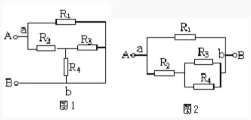
Decision. Let us assume that current comes from terminal A, diverges at point a, connects at point b and flows out of terminal B. The potentials of points a-R1-b and a-R2-R3(R4)-b of branches decrease in series, and voltages between points a and b of two branches are equal, so it is known that R3 and R4 are connected in parallel and connected in series with R2, and then connected in parallel with R1, equivalent circuit is shown in figure 2.
Flip Stretch Method
This operation can often be done when connecting circuits in lab. A non-interfering wire can be lengthened or shortened, or reversed, or a branch can be flipped to a different location. When reversed, two ends of branch remain unchanged. ; Wires can also slide over other wires from their nodes, but not over components. This allows us to simplify scheme, which we call telescopic flip method.
Example: Draw equivalent circuit in Figure 3.
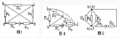
Decision. First, shorten wire connecting nodes a and c, and extend wire connecting nodes b and d beyond branch R3-C-R4, as shown in fig. 4.
Next, compress wire connecting nodes a and c to one point, compress wire connecting nodes b and d to one point, and connect R5 to extended wire of node d (fig. 5). It can be seen that R2, R3 and R4 are connected in parallel and then connected in series with R1 and R5 and connected to power supply.
Current direction method
Electric current is at heart of circuit analysis. Starting at positive pole of power supply (a passive circuit can think of current flowing from one end to other end), follow direction of current and follow external circuit through each resistor to negative pole of power supply. In series, all resistors through which current has branches are respectively connected in parallel.
Example. Try drawing equivalent circuit shown in Figure 6.
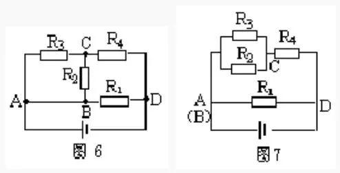
Solution: The current flows from positive pole of power supply and divides into three paths through point A (wire AB can be shortened to one point), passes through external circuit in a circle and flows into negative pole of power supply from point D. The first path leads straight to point D via R1, second road leads to point C via R2, and third road leads to point C via R3 Obviously, R2 and R3 are connected in parallel between two points AC. 2. The currents of three circuits converge at point C and reach point D through R4. It can be seen that R2 and R3 are connected in parallel, then connected in series with R4, and then connected in parallel with R1, as shown in fig. Figure 7.
Equipotential method
In more complex circuits, you can often find points with same potential, reduce all points with same potential to one point, or draw them on a line segment. When there is a non-feeding element between two equipotential points, it can be removed and ignored; when there is no power or current on a branch, branch can be cancelled. We call this simple circuit method equipotential method.
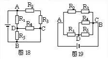
Example: as shown in figure 8, given that R1 = R2 = R3 = R4 = 2 ohms, find total resistance between A and B.
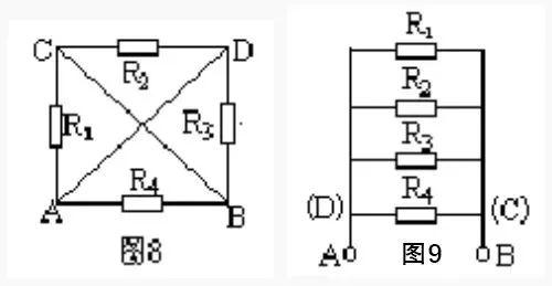
Decision. Imagine that two points A and B are connected to positive and negative poles of a power supply for analysis. The potentials of points A and D are equal, and potentials of points B and C are also equal. Draw two line segments respectively. Resistor R1 is connected to two points A and C, that is, connected to two points A and B; R2 is connected to two points C and D, that is, connected to two points B and A; R3 is connected to two points D and B, that is, connected to two points A and B, R4 is also connected to two points A and B, it can be seen that all four resistors are connected in parallel between two points A and B (Fig. 9). Therefore, PAB=3 ohms.
Branch node method
A node is a meeting point for several branches of a chain. The so-called branch node method consists in numbering each node (the convention: positive pole of power supply is first node, and nodes passing from positive pole to negative pole of power supply, respectively 1, 2, 3 ...), and branches starting from first node Road, lead to negative pole of power supply. There can be multiple branches (regulation: different branches cannot pass through same resistor multiple times), which can reach negative pole of power supply. The drawing principle is to first draw a branch with a small number of nodes, and then draw a branch with a large number of nodes. Then, following this principle, draw a branch, starting from 2nd node. By analogy, for rest of time, finally draw remaining resistors according to positions of their two ends.
Example: Draw equivalent circuit shown in Figure 10.
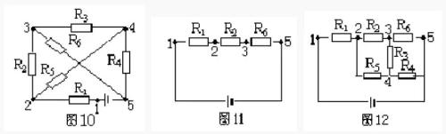
Decision. In Figure 10, there are five nodes 1, 2, 3, 4, and 5. According to principle of node-branch method, there are two branches with a small number of nodes coming out of positive pole of power supply (node 1): branches R1, R2, R5 and branches R1, R5, R4. Take one of branches R1, R2, R5 and draw it as shown in Figure 11.
Starting from second node, there are two branches reaching negative pole, one is R5, R4, number of nodes is 3, other is R5, R3, R5, number of nodes is 4, and existing R6 cannot be repeated. Therefore, branches R5 and R4 must be drawn again, and finally remaining resistance R3 must be drawn, as shown in Figure 12.
Geometric deformation method
Geometric deformation method is to geometrically deform a given circuit according to characteristics that wires in circuit can be arbitrarily lengthened, shortened, rotated or moved, to further determine relationship of circuit components and draw an equivalent electrical circuit.
Example: Draw equivalent circuit in Figure 13.
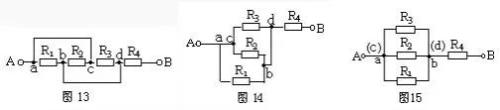
Solution: shorten ac branch wires and geometrically deform circuit to make figure 14, then compress ac into one point and bd into one point, obviously R1, R2 and R5 are connected in parallel and then in series with R4 (fig. . 15).
Remove resistance method
According to characteristics of series-parallel circuits, in a series circuit, if any resistor is removed and no current flows through other resistors, then those resistors are connected in series; in a parallel circuit, if any resistor is removed, other resistors are still left, current flows, these resistors are connected in parallel.
Example: still take fig. 13 as an example, assuming current comes from terminal A and flows out from terminal B, first remove R2 as shown in fig. 16, current flows through R1 and R3. By removing resistor R1, from fig. 17 shows that current is still flowing through resistors R2 and R3. Similarly, when resistor R3 is removed, current also flows through R1 and R2. From characteristics of parallel circuit, it can be seen that R1, R2 and R3 are connected in parallel and then connected in series with R4.
Independent Branch Method
Let current flow from positive pole of power supply. Following principle of not re-passing through same component, see how many paths flow back to negative pole of power supply, and then are several independent branches. The remaining resistance, not included in independent branch, is filled in accordance with positions of its two ends. When using this method, select an independent branch to include wire.
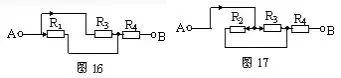
Example: Draw equivalent circuit shown in fig. 18.
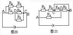
Scheme 1. Select A-R2-R3-C-B as an independent branch, A-R1-R5-B as another independent branch, and connect remaining resistor R4 between D and C. As shown in Figure 19.
Scheme 2: Select A-R1-D-R4-C-B as an independent branch and arrange positions R2, R3 and R5 respectively to form equivalent circuit diagram 20.
Diagram 3. Select A—R2—R3—C—R4—D—R5—B as an independent branch, then connect R1 to AD, and connect wire between C and B as shown in figure. Figure 21, results cannot yet intuitively judge series-parallel connection of resistors, so when choosing independent branches, non-pulse wires must be taken into account.
Node union method
Number nodes in known circuit and label them 1, 2, 3... in ascending order of potential from high to low (the node connected to positive pole of power supply has highest potential, and node connected to negative pole of power supply has highest potential. The potential of node is smallest, and nodes with equal potential use same amount and merge into one point). Then rearrange nodes according to potential level, and then connect components between corresponding two nodes to draw an equivalent circuit.
Example: Draw equivalent circuit shown in Figure 22.
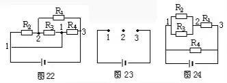
Decision. The node numbers are shown in Figure 22. Arrange nodes, arrange nodes 1 and 23 in a straight line at intervals as shown in Figure 23. The components return to their original position as shown in Figure 22, and equivalent circuit of resistors R1, R2, R3 and R4 between nodes 1 and 2 is shown in Figure 24.
Counter extraction method
When connecting a complex circuit to an ammeter, when influence of internal resistance of ammeter A and voltmeter V is neglected, since internal resistance of ammeter is zero, it can be removed and replaced with an unobstructed wire; due to internal resistance of voltmeter, it is extremely high and can be removed as an open circuit. Use above method to obtain equivalent electricity. Once connection ratio is established, add an ammeter to appropriate position in circuit.
Example: In circuit shown in figure 25, influence of internal resistance of meter is negligible, try to draw its equivalent circuit.
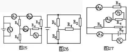
Decision. First cut off current, replace it with a wire, and then remove voltmeter as an open circuit, as shown in fig. 26. Then connect ammeter and voltmeter to appropriate positions in circuit according to figure 25, as shown in figure 27.
Related
- Senior engineer summarizes 10 methods for complex circuit analysis
- Senior EMC Engineer Resume: EMC Troubleshooting Process and Common Problems
- Several Effective Circuit Analysis Techniques
- Three common grounding methods in circuit design
- Experience in recognition of circuit diagrams of electronic circuits and method of circuit analysis
- Analysis of power circuit of a classic single-chip microcomputer
- Circuit Analysis of 6 Examples Explaining Lightning Surge Protection in Detail
- Analysis of damping RC circuit of a switching power supply "haberdashery"
- Principal analysis of BUCK / BOOST circuit, a summary is also in place
- Frequently Asked Questions for USB Interface Circuit Design
Hot Posts
 How to distinguish induction from leakage, we will teach you three tricks! Ordinary people can also learn super practical
- What is drowning in gold? Why Shen Jin?
- This is a metaphor for EMI/EMS/EMC that can be understood at a glance.
- How many types of pads have you seen in PCB design?
- Summary of Common PCB Repair Techniques
- What is three anti-paint? How to use it correctly?
- Knowing these rules, you will not get confused looking at circuit diagram.
- How to make anti-interference PCB design?
- Can diodes do this?