Location:Home Page > Archive Archive
What is difference between TVS tube and zener diode?
2023-03-28【Archive】
Zener Diode
A. Principle
It works in a reverse voltage breakdown state. When reverse voltage reaches and exceeds a stable voltage, reverse current suddenly increases while voltage across diode remains constant.
B. Classification
Separate from voltage regulator level: low voltage zener diode (<40V); high voltage zener diode (>200V)
Made of material: type N, type P
C. Main parameters
①VZ stable voltage: with specified voltage regulator tube and reverse operating current IZ, corresponding reverse operating voltage;
②DC IE;
③Dynamic resistance rZ;
④Maximum power dissipation PZM;
⑤Maximum stable operating current IZmax and minimum stable operating current IZmin;
⑥Temperature coefficient, higher temperature, larger voltage regulation error.
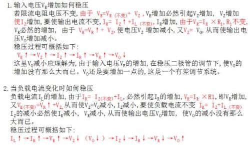
D. Goal
①Clamp protection on drain and source
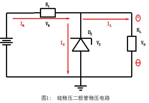
The silicon zener voltage regulator circuit uses inverse breakdown characteristic of zener diodes to stabilize voltage. Because of steep inverse characteristics, a large change in current will cause only a small change in voltage.
TVS for short
(transient voltage suppressor)
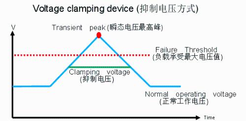
1. Functions
Under indicated reverse application conditions, when it is subjected to a high-energy transient overvoltage pulse, its operating resistance can immediately drop to a very low conductance value, which allows a large current to be passed and voltage to be clamped to a predetermined level. to effectively protect precision electronic circuit components from damage. Fast response speed (pS level), small size, low clamping voltage, high reliability. Bidirectional TVS is suitable for AC circuits and unidirectional TVS is generally used for DC circuits.
2. Classification
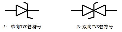
By polarity, it is divided into two types: monopolar and bipolar.
3. Symbol: Symbol
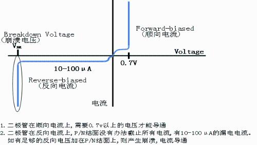
4. Diode characteristics table
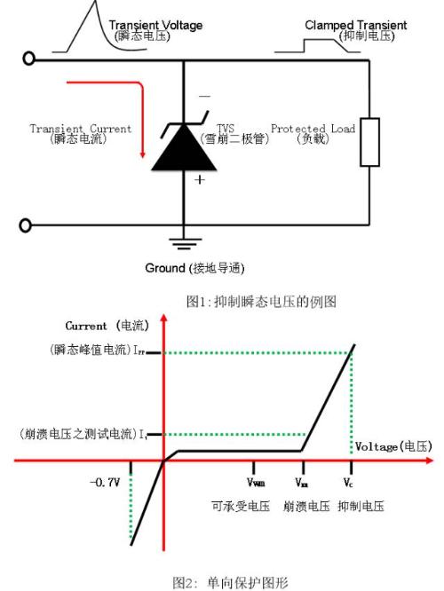
5. Examples of transient voltage suppression and unidirectional diode protection plots
6. TVS main parameters
① VBR: reverse breakdown voltage (reverse breakdown voltage is breakdown voltage)
Definition: When specified current of 1 mA (IR) flows through TVS, voltage VBR between two poles of TVS is minimum avalanche voltage of TVS. At 25°C, up to this voltage, TVS does not conduct current. When transient voltage exceeds VBR, transient voltage suppression diode is destroyed to suppress transient voltage to a certain level, providing ultra-low resistance transient current. , so that transient current is diverted through transient voltage suppression diode, bypassing protected components.
② IR: Reverse Leakage Current
When maximum reverse operating voltage is applied to TVS, TVS tube has a leakage current IR, typically reverse leakage current is 10-100µA. This leakage current is an important parameter when using TVS in high impedance circuits.
③VRWM: Maximum Reverse Operating Voltage (Stagnation Reverse Voltage: Permissible Reverse Voltage) is value of voltage at both ends of device at specified IR when device is working in reverse direction. At this time, diode is in a non-conducting state, usually VRWM=(0.8~0.9)VBR. When using VRWM, it must not be below normal operating voltage of protected device or line.
④ VC(max): maximum clamping voltage (TVS diode clamping voltage: suppression voltage)
Under influence of pulse peak current Ipp, maximum voltage on device is called maximum clamping voltage. When used, VC(max) must not exceed maximum allowed safe voltage of protected device. The ratio of maximum clamping voltage to breakdown voltage is called clamping factor. That is: clipping ratio = VC (max) / VBR. The overall restriction factor is about 1.3.
⑤ Transition Diode Capacitance Cj:TVS (Transition Diode Capacitance Value)
TVS capacitance is determined by silicon chip area and bias voltage. In case of zero bias, capacitance value tends to decrease with increasing bias voltage. The size of capacitor affects response time of TVS device. The larger capacitance of transient voltage suppression diode, more noise in circuit, more noise, or greater attenuation signal strength. For a circuit with a higher data/signal frequency, capacitance value should not exceed 10 pF. .
⑥ IPP: maximum peak surge current.
When operating in reverse, under given pulse conditions, maximum peak pulse current that device will carry.
⑦ PPR: Reverse Pulse Peak Power.
PPR TVS depends on peak pulse current IPP and maximum clamping voltage VC, in addition, it is also related to pulse shape, pulse width and ambient temperature.
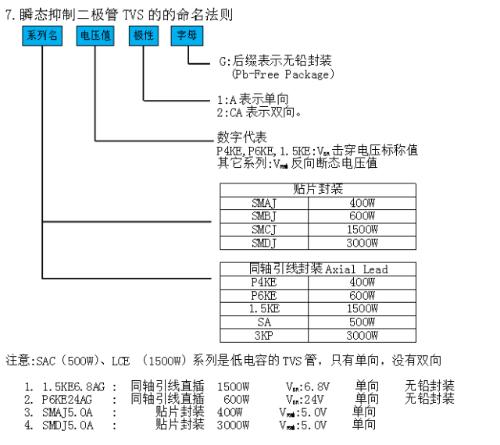
7. TVS nomenclature
8. Diode detection method
Use R×1k multimeter block to measure tubing quality:
①For unipolar TVS, according to measurement method of ordinary diodes, you can measure its forward and reverse resistance. Generally, forward resistance is about 4k5, and reverse resistance is infinite.
②For TVS with bidirectional pole, resistance value between two pins must be infinite when red and black probes are arbitrarily replaced, otherwise it means that tube function is bad or damaged.
9. Typical applications of TVS in circuits
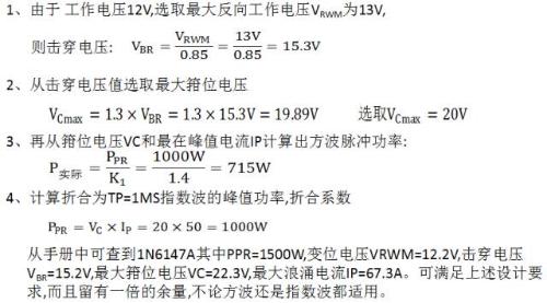
Example of DC selection:
The DC operating voltage of whole machine is 12V, maximum allowable safe voltage is 25V (peak value), overvoltage source impedance is 50MΩ, interference waveform is a square wave, TP=1ms, and maximum peak current is 50A .
AC circuit application examples:
Unidirectional transient suppression diodes should be used for DC lines, while bidirectional transient suppression diodes should be used for AC lines. AC is mains voltage, and transient voltage generated here is random, and lightning strikes (transient voltage generated by lightning induction) sometimes occur, so it is difficult to quantify instantaneous surge power PPR. But there must be a correct selection of maximum reverse operating voltage. The general principle is to multiply AC voltage by 1.4 to select maximum reverse operating voltage of TVS tube. The DC voltage is 1.1 to 1.2 times to select maximum reverse working voltage VRWM of TVS tube. The figure below shows a circuit diagram of a microcomputer power supply using TVS as line protection.
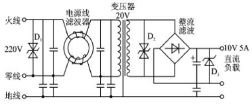
1. Add a 220VAC TVS tube to incoming line to suppress peak noise on 220VAC power line.
2. Add a noise filter to input line of transformer to filter out small noise peaks.
3. Add a TVS tube to output terminal of transformer at VAC = 20V to suppress noise again.
4. When output voltage of 10VDC is reached, a TVS tube is added to suppress interference.
Related
- What is difference between TVS tube and zener diode?
- What is difference between synchronous rectification and non-synchronous rectification?
- What is difference between thermocouple and RTD? Remember these points, do not choose wrong
- What is difference between 0 ohm resistors, inductors and magnetic balls for single point grounding?
- What is difference between surge device, lightning arrester, leakage protection, circuit breaker and circuit breaker? Come and get knowledge
- What is difference between 0 ohm resistors, inductors and magnetic balls? After reading this I finally got the answer
- What is difference between stepper/brush/brushless motors? remember this list
- You will understand difference between input impedance and output impedance after reading this article!
- You will understand difference between input impedance and output impedance by reading this article.
- TVS choice, this experience is comfortable
Hot Posts
 How to distinguish induction from leakage, we will teach you three tricks! Ordinary people can also learn super practical
- What is drowning in gold? Why Shen Jin?
- This is a metaphor for EMI/EMS/EMC that can be understood at a glance.
- How many types of pads have you seen in PCB design?
- Summary of Common PCB Repair Techniques
- What is three anti-paint? How to use it correctly?
- Knowing these rules, you will not get confused looking at circuit diagram.
- How to make anti-interference PCB design?
- Can diodes do this?