Location:Home Page > Archive Archive
TVS choice, this experience is comfortable
2023-04-12【Archive】
When it comes to TVS, most electronics engineers basically know that it is used to protect a port, to prevent damage to downstream circuit by a momentary port surge. However, due to its extremely important position in circuit for TVS selection process, many manufacturers directly recommend circuit and tell designer which device to choose, but rarely provide theoretical calculations for selection process. When some electronic engineers choose TVS models, old people rely on experience, and beginners to recommendation. After changing manufacturer or test conditions, they will not be able to start. This article specifically addresses this problem so that beginners and old people can easily select TVS models.
It's all about tension, why are other people's choices better than mine?
01 How it works
TVS (Transient Voltage Suppressors), that is, transient voltage suppressors, also known as avalanche breakdown diodes. This is an integrated device with one PN junction or several PN junctions, made in semiconductor technology. TVS can be divided into unidirectional and bidirectional. Unidirectional TVS are usually used in DC supply circuits, and bidirectional TVS - in AC voltage circuits. As shown in Figure 1, in case of a DC circuit, a unidirectional TVS is connected in reverse-parallel circuit. During normal circuit operation, TVS is in a cut-off state (high impedance state), which does not affect normal operation of circuit. When circuit has an abnormal overvoltage and reaches TVS (avalanche) breakdown voltage, TVS quickly changes from a high resistance state to a low resistance state, discharging instantaneous overload current caused by abnormal overvoltage to ground and fixing abnormal overvoltage. at same time.Lower level to protect downstream circuit from abnormal overvoltage damage. When abnormal overvoltage disappears, TVS resistance returns to a high impedance state.
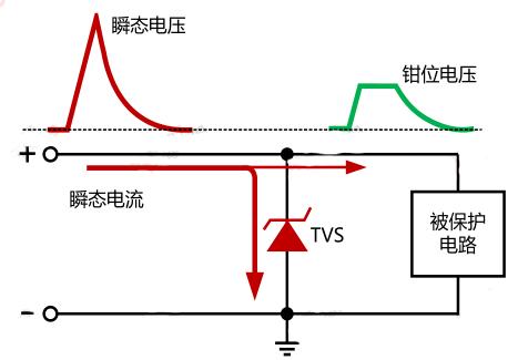
Figure 1. How TVS works
02 key parameters
If a worker wants to do his job well, he must first sharpen his tools. To use TVS well, he must first understand its basic parameters.
(1) Trip Voltage Vrms
The highest TVS operating voltage, maximum peak operating voltage, or peak DC voltage that can be applied continuously without causing degradation or damage to TVS. For AC voltage, it is represented by effective value of highest operating voltage. With VRWM, TVS is considered inoperative, that is, non-conductive. In other words, maximum operating voltage of circuit must be less than Vrwm, otherwise it will trigger TVS and cause circuit to work abnormally.
(2) Leakage current I R
Leakage current, also known as standby current. The maximum current flowing through TVS at specified temperature and maximum operating voltage. Leakage current TVS is usually measured at cutoff voltage, for a certain type of TVS I R must be within specified range of values. The value of voltage applied to both ends of TVS is V RWM and value of current read from ammeter is leakage current I R TVS. For fuel assemblies of same power and voltage at VRWM ≤10V, leakage current of bidirectional fuel assemblies is twice that of unidirectional fuel assemblies. For some analog ports, leakage current will affect AD sampling value, so lower TVS leakage current, better.
(3) breakdown voltage VBR
Breakdown voltage refers to voltage across TVS measured on current-voltage curve at specified pulsed DC current IT or near avalanche current conditions. The test current is usually chosen to be about 10 mA and current injection time should not exceed 400 ms so as not to damage device. VBR MIN and VBR MAX is breakdown voltage deviation TVS, and usually TVS is deviation. ±5%. When measured, V BR is between V BR MIN and V BR MAX This is considered a qualified product.
(4) I peak surge current, clamping voltage V C
Peak surge current, peak value of specified surge current waveform. TVS typically use a 10/1000 µs current waveform. Clamping voltage, peak voltage measured at TVS while applying peak impulse current I PP of given waveform. I PP and V C are parameters to measure ability of TVS to withstand surge current and overvoltage in protection circuit, and these two parameters are interrelated. For clamping characteristics of TVS in lightning protection circuit, you can refer to parameter V C. For same type of TVS, smaller VK for same I PP, better clamping characteristics of TVS. Shock resistance of impulse current TVC can be attributed to I pp, for fuel assemblies of same type, more I pp, stronger impact resistance of pulsed current.
(5)Cut capacitance CI, leakage current Ir
The junction capacitance is parasitic capacitance in TVS. You should pay attention to it when protecting high-speed I / O ports. Excessive junction capacitance can affect quality of signal. Leakage current mainly results in power loss or in an analog signal affects sampling value of AD signal.
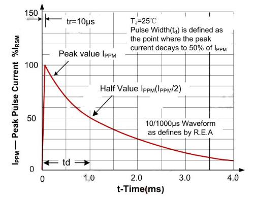
Figure 2. Manufacturers typically provide a 10/1000 µs test waveform
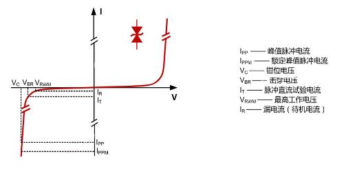
Figure 3. Basic TVS parameters
03 Selection Process
After understanding basic parameters of a TVS, we will begin most important process of choosing a TVS. Before selecting TVS, we must first understand ultimate goal of selection:
1. Appropriate voltage can protect downstream circuit;
2. The junction capacitance of injected TVS cannot affect circuit;
3. The power reserve of fuel assemblies is sufficient to comply with test standards, and it cannot be hung in front of fuse.
The selection process can be carried out according to following steps:
1. Select maximum operating voltage Vrmw TVS;
2. Select TVS VC clipping voltage;
3. Select TVS power;
4. Evaluate effect of leakage current Ir;
5. Evaluate effect of transition capacitance.
【Select maximum operating voltage Vrmw for TVS】
During normal operation of circuit, TVS should not work, that is, it is in a cut-off state, so cut-off voltage of TVS must be greater than maximum operating voltage of protected circuit. Thus, it can be guaranteed that TVS will not affect operation of circuit during normal operation of circuit. However, TVS operating voltage also determines TVS clamping voltage. When cut-off voltage is greater than normal line operating voltage, TVS operating voltage cannot be selected too high. ability of subsequent circuit. It is required that Vrwm be greater than operating voltage, otherwise operating voltage greater than Vrwm will cause an increase in reverse leakage current TVS close to conduction or avalanche, which will affect normal operation of circuit. When looked at comprehensively, Vrwm can refer to following formula:
Vrwm≈1.1~1.2*VCC, -------- where VCC is maximum operating voltage of circuit.
【Select TVS VC clipping voltage】
The clamping voltage of fuel assemblies must be below maximum transient safe voltage that protected circuit of next stage can withstand, VC is proportional to avalanche breakdown voltage of fuel assemblies and I p. For TVP of same power level, higher breakdown voltage, higher Vk, and maximum clamping voltage Vk of selected TVP cannot be greater than maximum voltage that protected circuit can withstand. Otherwise it will damage circuit when TVS is clamped to Vc. Vc can refer to following formula:
VC
【Select TV power Pppm (or Ipp)】
The rated transient power of TVS products must be greater than maximum transient power that can occur in circuit. Theoretically, higher TVS power, thebetter, and it can withstand more energy and impact time. However, higher power, higher TVS pulse power. The larger package, higher price, so TVS power can meet requirements. For fuel assemblies of different power, fuel assemblies with same voltage characteristics have same value of V C, but I PP is different. Therefore, Pppm is directly proportional to Ippm, more Ippm, more Pppm. For a particular circuit, there are corresponding test requirements, if maximum test current in a real circuit is Iactual, then Iactual can be estimated as:
Iactual=Uactual/Ri; ---------, where Uactual is test voltage, Ri is test internal resistance.
TVS must pass test, so in real circuit minimum power required is P fact TVS at 10/1000 µs waveform: ------- where di/dt is waveform conversion factor if actual test waveform is different Waveform If waveform is 8/20us, it is recommended to select di/dt. If test signal is 10/1000 µs, take it. When actually selected, TVS should have a certain margin, and PPMP power for TVS should be selected according to Pppm>Pactual.
Evaluate impact on junction capacitance and leakage current of selected TVS
If TVS is used to protect high-speed I/O ports, analog signal sampling, and applications with low power equipment, effects of junction capacitance and leakage current must be considered. The smaller settings, better.
04 Selection example
All data is boring, let's take a real case as an example:
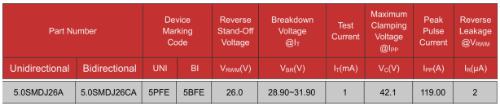
The normal operating voltage VCC of circuit is 24V, maximum operating voltage Vmax is 26V, maximum transient voltage that downstream circuit can withstand is 50V, experimental test waveform is 8/20µs, test voltage is 500V. , and internal resistance of test power supply and static resistance of PPTC add up to 2 ohms. Select appropriate TVS based on information above.
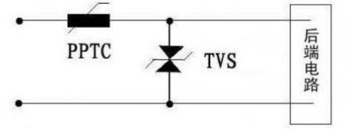 Rice. 4. Sample Design
1) Select maximum operating voltage TVS
Vrmw≈1.1~1.2*VCC=26~28V
2) Select TVS clipping voltage
VC
3) Calculate actual power of test signal:
Pact=50*(500/3)*1/2=4166W
According to calculation results, TVS 5.0SMDJ26A can be selected. Since this TVS is used in power port, junction capacitance and leakage current can be practically neglected.
Related
- TVS choice, this experience is comfortable
- What is difference between TVS tube and zener diode?
- Surprisingly, this is most prone to PCB failure?
- Is applying an LC resonant circuit too complicated? Actually this step is very important.
- About resistors, this is what you need to know
- The SD card is broken, can it be fixed this way?
- What is difference between stepper/brush/brushless motors? remember this list
- This is a metaphor for EMI/EMS/EMC that can be understood at a glance.
- Engineer Daniel tells you: The "Y Capacitor" of a switching power supply is calculated in this way.
- What is difference between 0 ohm resistors, inductors and magnetic balls? After reading this I finally got the answer
Hot Posts
 How to distinguish induction from leakage, we will teach you three tricks! Ordinary people can also learn super practical
- What is drowning in gold? Why Shen Jin?
- This is a metaphor for EMI/EMS/EMC that can be understood at a glance.
- How many types of pads have you seen in PCB design?
- Summary of Common PCB Repair Techniques
- What is three anti-paint? How to use it correctly?
- Knowing these rules, you will not get confused looking at circuit diagram.
- How to make anti-interference PCB design?
- Can diodes do this?