Location:Home Page > Archive Archive
In digital form? Imitation? Don't get confused by engineering design
2023-04-21【Archive】
In engineering design, from point of view of reference level, they are all same ground, and they must be connected together to obtain same reference potential. Ground separation is mainly in terms of wiring to reduce interference between different circuits, and power supply ground cannot be considered as an analog ground, and signal ground cannot be considered as a digital ground.
This is mainly done to divide ground according to characteristics of circuit. The 3.3V digital signal circuit may also require separating ground of 2.5V circuit and 5V circuit. Even if power is supplied to same digital circuit, there are sometimes wiring requirements, such as grounding high current I/O part which may require separate processing.
Ground usually refers to chassis and this part needs ESD protection and protection. Sometimes circuit ground is connected to case through a 1M resistor, and sometimes it is connected directly. Handle according to ESD application and requirements.
In short, a distinction must be made between characteristics of a logical ground connection and physical characteristics of a printed circuit board. Theoretically, there is 0 voltage on ground, but there is a lot of noise and bounce on a real PCB.
Separating and connecting ground. Grounding is one of important means of suppressing electromagnetic interference and improving electromagnetic compatibility performance of electronic equipment. Proper grounding can not only improve product's ability to suppress electromagnetic interference, but also reduce external electromagnetic radiation of product.
Meaning of ground. "Ground" of electronic equipment usually has two meanings, one is "ground" (safety ground) and other is "system reference ground" (signal ground). . Grounding refers to creating a low-resistance conductive path between system and a defined potential reference plane. "Connecting to ground" means using ground potential as a reference and ground as ground potential to connect metal enclosure of electronic equipment and circuit reference point to ground.
Connecting ground plane to earth is often driven by following considerations:
A. Improve stability of equipment chain system;
B, electrostatic discharge;
C. Ensure safety of personnel.
Ground classification:Digital ground, Analog ground, Signal ground, AC ground, DC ground, Shield ground, Floating ground
In addition to correct design and installation of grounding, it is also necessary to properly handle grounding of various signals. The control system has approximately following ground wires:
(1) Digital ground: also called logic groundearth, this is zero potential of various switching (digital) signals.
(2) Analog ground: ground potential of various analog signals.
(3) Signal ground: usually a sensor ground.
(4) AC Ground: The ground wire of AC power supply, which is usually a noisy ground.
(5) DC Ground: Ground DC power supply.
(6) Shield ground: Also called chassis ground, it is designed to prevent electrostatic induction and magnetic field induction.
The handling of above ground wires is an important consideration in design, installation and commissioning of system. Here are some opinions about grounding:
(1) The control system must be grounded at one point. As a general rule, high frequency circuits should be earthed at several points nearby, and low frequency circuits should be earthed at one point. In low-frequency circuits, inductance between wiring and components is not a big problem, but interference of ground loop is a big influence, so a single point is often used as a ground point, but a single-point ground is not suitable. for high-frequency, because at high frequency at , there is inductance to ground, which increases impedance of ground wire, and at same time, an inductive coupling occurs between various wires. Generally speaking, if frequency is lower than 1MHz, single-point grounding can be used, if frequency is higher than 10MHz, multi-point grounding can be used, between 1MHz and 10MHz, single-point grounding and multi-point grounding can be used. grounding can also be used.
(2) AC ground and signal ground cannot be used together. Since there will be several mV or even several V between two points of power supply ground wire, these are very serious interference to low level signal circuits, so they must be isolated and prevented.
(3) Comparison of buoyancy and grounding. The whole machine floats, that is, all parts of system float with ground. This method is simple, but insulation resistance between entire system and ground should not be less than 50 MΩ. This method has a certain anti-interference ability, but once insulation falls, it will cause interference. Another way is to ground case and leave rest floating. This method has strong anti-jamming, safe and reliable, but it is more difficult to implement.
(4) Analog ground. The way you connect analog ground is very important. Floating shielding technology can be used for analog signals to improve common mode immunity. Grounding specific analog signals must be done in strict accordance withTVI with requirements of instruction manual.
(5) Shield ground. In control system, in order to reduce capacitive coupling noise in signal, as well as accurately detect and control it, it is very necessary to take measures to shield signal. Depending on purpose of shielding, method of connecting shield ground also differs. Shielding electric field solves problem of distributed capacitance and is usually connected to ground; electromagnetic field shielding basically avoids interference from high frequency electromagnetic field radiation such as radars and radios. It is made of metal with low resistance and high conductivity and can be grounded. Magnetic field shielding is used to prevent magnetic induction of magnets, motors, transformers, coils, etc. The shielding method is to use high magnetic permeability materials to complete magnetic circuit, and it is generally better to connect to ground.
When signal circuit is grounded at one point, shielding layer of low frequency cable must also be grounded at one point. If protective layer of cable is located in several places, noise current will be generated and a source of noise interference will be formed. When circuit has an ungrounded signal source connected to a grounded amplifier in system, shield at input must be connected to common of amplifier; conversely, when a grounded signal source is connected to an ungrounded amplifier in system, amplifier's input terminal must also be connected to signal source's common terminal.
In order to ground an electrical system, it should be classified according to requirements and purposes of grounding. Different types of grounding cannot be simply and arbitrarily interconnected, but must be divided into several independent grounding subsystems, each of which has its own common Grounding points or grounding trunks of grounding lines at end are connected to each other, and a common grounding is performed.
B1
Why grounding?
Answer: The introduction of grounding technology was originally a protective measure to prevent electrical or electronic equipment from being struck by lightning to protect buildings. At same time, grounding is also an effective means of protecting personal safety, when phase wire (such as poor wire insulation, aging lines, etc.) touches equipment body for any reason, a dangerous voltage will be generated on equipment body, thus , generated short circuit current will flow through protective earth line to earth, thus playing a protective role.
With development of electronic communications and other digital fields, it is far from sufficient to consider only lightning protection and safety in grounding system. For example, in a communication systemcommunicating signals between a large number of devices requires each device to have a reference "ground" as signal reference ground. In addition, with complexity of electronic equipment, frequency of signal becomes higher and higher, so when designing grounding, special attention must be paid to electromagnetic compatibility issues such as mutual interference between signals, otherwise improper grounding will seriously affect reliability. work system sex and stability. Recently, concept of "ground" has also been introduced into high-speed signal return technology.
B2
Ground Definition
Answer: In modern grounding concepts for line engineers, term usually means "line voltage reference point"; for system designers, this is often a cabinet or rack; for electrical engineers, this means a green protective earth or ground connection. A more general definition is that "ground is a low impedance path through which current returns to its source". Note that the requirements are "low impedance" and "access".
B3
Common ground symbols
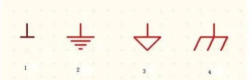
Answer:PE, PGND, FG - protective earth or chassis; BGND or DC-RETURN - DC - 48V (+24V) power supply (battery) reverse; GND - working ground; DGND - Digital ground, AGND - analog ground, LGND - lightning protection ground GND is often specified as a voltage reference point in a circuit.
In an electrical sense, GND is divided into power ground and signal ground. PG is short for Power Ground. The other is SignalGround (signal ground). In fact, they may be related (not necessarily mixed!). These two names are mainly intended to make it easier to parse circuit.
There are also two types of ground that must be distinguished due to different shapes of circuits: digital ground and analog ground.
Both digital and analog grounds have a signal ground and a power ground. Between digital ground and analog ground, some circuits can be connected directly, some circuits must be connected to a choke, and some circuits cannot be connected.
B4
Proper grounding
Answer: There are many grounding methods, including single-point grounding, multi-point grounding, and mixed grounding types. Single-point grounding is divided into serial single-point grounding and parallel single-point grounding. Generally speaking, single-point grounding is used for simple circuits, grounding differences between various functional modules, and low-frequency (f<1MHz) electronic circuits. When designing high-frequency (f>10 MHz) circuits, it is necessary to use multi-point grounding or multi-layer boards (full ground layers).
B5
Introducing backflow and cross-segmentation
Answer: An electronic signal needs to find a way for least impedance current to flow back to ground, so how to deal with this signal backflow becomes very important.
First, from formula you can find out that radiation intensity is proportional to area of the loop, that is, longer return path must go, more ring is formed, and more interference with external radiation, so when PCB is laid out, area of the power circuit and signal circuit must be reduced as much as possible.
Secondly, for a high speed signal, providing a good signal return can ensure its signal quality, this is because characteristic impedance of a transmission line on a PCB is usually based on ground layer. (or power level) is calculated as a reference. If there is a continuous ground plane near a high-speed line, line's impedance can remain continuous. If there is no ground near segment line, impedance will change and discontinuous impedance will thus affect integritysignal strength.
Thus, when wiring, high speed line should be placed on a layer close to ground plane, or one or two ground lines should be laid in parallel next to high speed line to perform function of shielding and allowing reverse flow nearby.
Third, why are you trying not to share power supply when wiring? This is also because once signal crosses different power levels, its return path will be very long and easily disrupted. Of course, it is not strictly required that power supply cannot be shared. This is possible for low speed signals because generated noise can be ignored compared to signal. For high-speed signals, you must carefully check and try not to cross them. You can adjust power wiring.
B6
Why separate analog and digital lands and how?
Answer: Both analog and digital signals must return to ground because digital signal changes rapidly and noise caused by digital ground will be very large, while analog signal needs a clean ground reference work. If analog and digital bases are mixed, noise can affect analog signal. Generally speaking, analog ground and digital ground must be processed separately and then connected together via thin traces or connected together at same point. The general idea is to try and block output of noise from digital ground to analog ground. Of course, it's not a very hard requirement that analog ground and digital ground should be separated. If digital ground next to analog part is still very clean, they can be connected together.
B7
How to ground signals on board?
Answer: For general purpose devices, nearest ground is best. After adopting multi-layer board design with a full ground layer, grounding common signals is very easy. The main principle: is to ensure trace continuity and reduce number of vias, proximity to ground plane or power plane, etc.
B8
How do I ground board's interface components?
Answer: Some boards have external input and output interfaces, such as serial port connectors, RJ45 network port connectors, etc. If ground design is not suitable for them, it will affect normal operation. such as bit errors and packet loss when connecting network ports, and it will become a source of external electromagnetic interference, sending noise inside board to outside. Generally speaking, independent interface ground is separated separately, and connection to signal ground is connected by a thin wire, and a 0Ω or 0Ω resistor can be connected in series.and little resistance. Thin traces can be used to block interference from signal ground to interface ground. Similarly, filtering of interface ground and interface power should be carefully considered.
B9
How to ground shield of a shielded cable?
Answer: The shielding layer of shielded cable must be connected to interface ground of board, not to signal ground, since there are various noises on signal ground. layer is connected to signal ground. Noise voltages can cause common mode currents outward along shield, which is why poorly designed cables tend to be biggest sources of EMI output noise. Of course, interface ground is also assumed to be very clean.
It is used for labeling in a hybrid circuit, VCC indicates analog power supply, GND indicates analog ground, VDD indicates digital power supply, and VSS indicates digital power supply ground.
VCC is basically a bipolar circuit power supply, and C is a collector collector. The power supply is usually connected to an NPN collector (or PNP emitter). When integrated circuit first appeared, there were only NPN tubes, and later integrated PNP tubes. VDD/VSS typically represent power supply and ground of MOS circuit, while D/S represent drain (drain)/source (source) of MOS lamp, respectively.
Finally, let's talk about general principles for choosing grounding methods:
For a given device or system, at highest frequency of interest (corresponding to wavelength ), when length of transmission line is L>in, it is considered as a high frequency circuit, otherwise it is considered as a low frequency circuit. As a rule of thumb, for circuits below 1 MHz, it is better to use a single-point ground, for circuits above 10 MHz, it is better to use a multi-point ground. For intermediate frequencies, a single point ground can be used to avoid common impedance coupling if length of longest transmission line, L, is less than /20 Ω.
Related
- In digital form? Imitation? Don't get confused by engineering design
- PCB design guidelines: safety regulations, layout and wiring, EMC, thermal design, process engineering.
- Knowing these rules, you will not get confused looking at circuit diagram.
- Three common grounding methods in circuit design
- Do not underestimate "form of high-frequency magnetic core" in switching power supply, what effect does it have on transformer?
- How many types of pads have you seen in PCB design?
- In circuit design, what are differences between six types of grounds?
- Do you know layout requirements of some special devices in PCB design?
- Hardware Circuit Design Specification: A Very Good Reference to Hardware Design
- Do you know four magical ways to use a digital multimeter?
Hot Posts
 How to distinguish induction from leakage, we will teach you three tricks! Ordinary people can also learn super practical
- What is drowning in gold? Why Shen Jin?
- This is a metaphor for EMI/EMS/EMC that can be understood at a glance.
- How many types of pads have you seen in PCB design?
- Summary of Common PCB Repair Techniques
- What is three anti-paint? How to use it correctly?
- Knowing these rules, you will not get confused looking at circuit diagram.
- How to make anti-interference PCB design?
- Can diodes do this?