Location:Home Page > Archive Archive
step-down capacitor pay attention to these six points, do not need to worry about circuit analysis
2023-03-18【Archive】
1. Select appropriate capacitor according to load current and AC operating frequency, not load voltage and power.
2. Current-limiting capacitors must use non-polar capacitors and electrolytic capacitors must not be used. And withstand voltage of capacitor must be above 400V. The most ideal capacitor is an oil capacitor in an iron case.
3. A step-down capacitor cannot be used in high power environments because it is unsafe.
4. A capacitive buck converter is not suitable for dynamic load conditions.
5. Similarly, capacitive step-down is not suitable for capacitive and inductive loads.
6. When DC operation is required, try using half-wave rectification. Bridge rectification is not recommended. And meet constant load conditions.
01
First cycle:
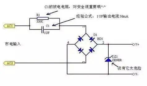
This type of circuit is typically used to provide non-isolated low current power supplies at a low cost. Its output voltage can typically range from a few volts to tens of volts, depending on zener diode used. The amount of current that can be provided is proportional to capacitance of current limiting capacitor. When using half-wave rectification, current (average value) that can be obtained per microfarad capacitance is: (SI unit)
I(AV)=0.44*V/Zc=0.44*220*2*Pi*f*C
=0.44*220*2*3.14*50*C=30000°C
=30000*0.000001=0.03 A=30 mA
If full-wave rectification is used, twice current (average value) can be obtained as:
I(AV)=0.89*V/Zc=0.89*220*2*Pi*f*C
=0.89*220*2*3.14*50*C=60000°C
=60000*0.000001=0.06 A=60mA
Typically, although full-wave rectification of this type of circuit has a slightly higher current, because of floating ground, stability and safety is worse than that of half-wave rectification, so it is used less frequently.
When using this scheme, note following:
1. It is not isolated from 220V AC high voltage, pay attention to safety and avoid electric shock!
2. A current-limiting capacitor must be connected to current-carrying wire, withstand voltage must be large enough (more than 400V), and a series of anti-shock and safety resistors, as well as parallel discharge resistors, must be added.
3. Pay attention to power consumption of Zener tube, and it is strictly forbidden to disconnect Zener tube.
02
Second cycle:
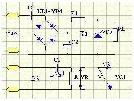
The simplest capacitive buck DC power supply circuit and its equivalent are shown in Figure 1. C1 is a step-down capacitor, typically 0.33-3.3uF. Suppose C1=2uF, its capacitance XCL=1/(2PI*fC1)=1592. Since on-state rectifier tube resistance is only a few ohms, dynamic resistance of VS regulator tube is about 10 ohms, current-limiting resistor R1 and load resistor RL are generally 100-200 ohms, and filter capacitor is usually 100uF ~ 1000uF, and its capacitance very small and can be neglected.
If R is used to represent equivalent resistance of all components except C1, you can draw equivalent AC circuit in figure. At same time, condition XC1>R is satisfied, so voltage vector can be drawn. Since R is much smaller than XC1, voltage drop VR across R is also much smaller than voltage drop across C1, so VC1 is approximately equal to supply voltage V, that is, VC1 =V. According to electrotechnical principle, ratio between average value of Id of rectified direct current and average value of I of alternating current is Id=V/XC1. If C1 is in uF, then Id is in milliamps. For AC 22 V, 50 Hz, you can get Id = 0.62C1.
The following two conclusions can be drawn from this:
(1) When using a power transformer as a power supply for rectifier, output voltage is constant when determining parameters in circuit, and output current Id changes with increasing or decreasing load;
(2) When using capacitor buck rectifier circuit, since Id=0.62C1, it can be seen that Id is proportional to C1, that is, after determining C1, output current Id is constant, while output DC voltage varies with load. The resistance value RL varies within certain limits. The smaller RL, lower output voltage, and larger RL, higher output voltage. The value of C1 must be selected according to load current. For example, load circuit requires an operating voltage of 9V and average load current is 75mA. Since Id = 0.62C1, it can be calculated that C1 = 1.2uF. Taking into account losses on regulator lamp VD5, C1 can be 1.5 uF, and actual current provided by power supply, Id = 93 mA.
The value of regulated voltage of zener diode must be equal to operating voltage of load circuit, and selection of its stable current is also very important. Since capacitive buck power supply provides constant current, which is roughly a constant current source, it is generally not afraid of short circuiting load, but when load is fully opened, entire current of 93 mA will pass through loops R1 and VD5, so maximum stability of VD5 The current should be 100mA . Since RL is connected in parallel with VD5, while ensuring that RL accepts 75 mA of operating current, VD5 still has 18 mA of current flowing through it, so its minimum stubThe strong current should not be more than 18mA, otherwise it will lose its voltage stabilizing effect.
The value of current-limiting resistor should not be too large, otherwise it will increase power loss and also increase C2 withstand voltage requirement. If R1 = 100 ohms and voltage drop across R1 is 9.3V, loss is 0.86W and a 100 ohm and 1W resistance can be used.
The filter capacitor is usually taken from 100 uF to 1000 uF, but care should be taken to select its resistance. As mentioned above, load voltage is 9V, voltage drop across R1 is 9.3V, and total voltage drop is 18.3V. With a certain margin, it is better that the withstand voltage of C2 be higher than 25V.
03
Third cycle:
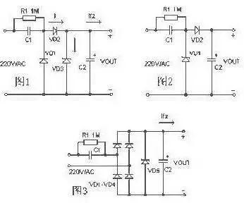
As shown in Figure 1, C1 is a step-down capacitor, D2 is a half-wave rectifier diode, D1 provides discharge circuit for capacitor C1 during mains negative half-cycle, and D3 is a zener diode. R1 discharges charge of C1 after power is turned off Install a resistor. In practical applications, circuit shown in Figure 2 is often used. When it is necessary to provide more current to load, bridge rectifier circuit shown in Figure-3 can be used. The unregulated DC voltage after rectification is usually higher than 30V and will fluctuate greatly when load current changes. This is due to large internal resistance of this type of power supply, so it is not suitable for high current power supply applications.
Device selection:
1. When designing a circuit, first measure exact value of load current, and then refer to example to select capacity of step-down capacitor. Because current Io supplied to load through step-down capacitor C1 is actually charging and discharging current Ic flowing through C1. The larger capacitance C1 and smaller capacitive reactance Xc, greater charging and discharging current flowing through C1. When load current Io is less than charge and discharge current C1, excess current will flow through Zener tube. Burn out.
2. To ensure safe operation of C1, its withstand voltage must be more than twice voltage of power supply.
3. The choice of discharge resistor R1 should ensure that charge on C1 is discharged within required time.
Design example:
In Figure 2, C1 is known to be 0.33uF and AC input voltage is 220V/50Hz. Find maximum current that circuit can supply to load.
The capacitance Xc of capacitor C1 in circuit is:
Xc=1/(2 πf C)= 1/(2*3.14*50*0.33*10-6)= 9.65K
The charging current (Ic) flowing through capacitor C1 is:
Ic = U / Xc = 220 / 9.65 = 22 mA.
Typically, relationship between capacitance C of step-down capacitor C1 and load current Io can be approximated as: C=14.5 I, where unit of capacitance C is µF and unit of Io is A.
The capacitive buck power supply is a non-isolated power supply. Particular attention should be paid to insulation to avoid electric shock.
The unregulated DC voltage after rectification is typically higher than 30V and will fluctuate greatly as load current changes. This is due to large internal resistance of this type of power supply, so it is not suitable for applications. high current power supply.
The capacitive buck power supply is a non-isolated power supply. Particular attention should be paid to insulation to avoid electric shock.
The principle of operation of a capacitive buck converter is not complicated. Its working principle isin use of capacitive reactance generated by a capacitor at a certain frequency of an AC signal to limit maximum operating current. For example, at a mains frequency of 50 Hz, capacitance generated by a 1 uF capacitor is about 3180 ohms. When 220V AC is applied to both ends of capacitor, maximum current flowing through capacitor is about 70mA. Although current flowing through capacitor is 70 mA, it does not create any power consumption across capacitor. It must be case that if capacitor is an ideal capacitor, current flowing through capacitor is current of imaginary part, and work it does is Reactive force.
According to this feature, if we connect a resistive element in series with a 1uF capacitor, voltage across resistive element and power consumed by it are completely dependent on characteristics of resistive element. For example, we connect a 110V/8W light bulb in series with a 1uF capacitor. When connected to AC 220V/50Hz, light bulb will light up and emit normal brightness without burning out. Since current required for a 110V/8W incandescent lamp is 8W/110V=72mA, it matches current limiting characteristics of a 1uF capacitor.
Similarly, we can also connect a 5W/65V light bulb and a 1uF capacitor in series to a 220V/50Hz AC power supply, and light bulb will also burn without burning out. Because working current of 5W/65V lamp is also about 70mA. So capacitive bucking actually uses capacitive reactance to limit current. The capacitor actually plays role of current limiting and dynamic voltage distribution between capacitor and load.
Related
- step-down capacitor pay attention to these six points, do not need to worry about circuit analysis
- What skills should I pay attention to when designing a triode amplifier circuit? (Easy to understand)
- Pay attention to PCB vias
- Did you pay attention to details of using relay?
- What is difference between thermocouple and RTD? Remember these points, do not choose wrong
- What you need to know about semiconductor chips
- The size, withstand voltage and direction of capacitor, how to choose these parameters?
- About resistors, this is what you need to know
- Please remember these 4 points to switch power supply in order to "comply with safety regulations".
- 7 things you need to know about high-speed linking and routing
Hot Posts
 How to distinguish induction from leakage, we will teach you three tricks! Ordinary people can also learn super practical
- What is drowning in gold? Why Shen Jin?
- This is a metaphor for EMI/EMS/EMC that can be understood at a glance.
- How many types of pads have you seen in PCB design?
- Summary of Common PCB Repair Techniques
- What is three anti-paint? How to use it correctly?
- Knowing these rules, you will not get confused looking at circuit diagram.
- How to make anti-interference PCB design?
- Can diodes do this?