Location:Home Page > Archive Archive
Does circuit diagram actually contain that much truth?
2023-04-19【Archive】
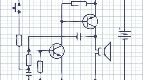
A wiring diagram is a wiring diagram of electronic components drawn using circuit component symbols. It details connection and direction of each component, a description of each pin, and some test data.
Schematic, also known as "electric circuit diagram". This type of diagram is commonly used in circuit design and analysis because it directly depicts structure and operation of electronic circuits. By analyzing a circuit, you can understand how it actually works by identifying symbols for various circuit components drawn on drawing and how they are connected. A circuit diagram is a diagram used to represent principle of operation of an electronic circuit.
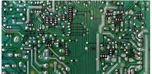
A PCB diagram is a cartographic drawing of a PCB that details PCB layout, component locations, etc.
When looking at a circuit diagram, first look at part of power supply to understand whether circuit is powered by AC or DC, a single power supply or multiple power supplies and voltage levels. After clarifying this, look at subcircuits. First, distinguish whether it is a digital circuit or an analog circuit. An analog circuit looks at receiving a signal to find out source of signal. There are radio frequency, audio, various sensors, instruments and other constant or pulse circuits current, voltage type or current type. Analyze function of follow circuit to find out if it is demodulation, amplification, shaping, or compensation. Finally, look at output circuitry, whether it be modulation or control. Digital circuits mainly analyze logic functions and circuit functions.
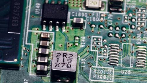
In order to understand a printed circuit board, it is best to be able to understand its electrical circuit diagram (i.e. circuit diagram), master marking method of electronic components and its working principle, and master normal operation of some commonly used components, parameters and role in a conventional circuit etc., and then analyze circuit board (called circuit board), you can quickly understand working principle of it and some situations that need to be mastered.
To analyze modules of a subcircuit, you need to find main components of each subcircuit (of course, you must be familiar with this component), find out electrical connection between modules of subcircuit, and finally, output and input or functions of entire circuit.
The circuit of whole machine has a certain function and is composed of various unit circuits. The unit circuits form signal processing branches with certain functions, and then these branches form entire machine circuit. First, you must find out what is function of circuit you see, what type of circuit it belongs to, whether it be an audio, video, digital or hybrid circuit; then use appropriate schema knowledge to interpret those schemas. ; , DC level is analyzed. The DC portion of circuit is basis for normal operation of circuit. The AC signal can only be processed after DC circuit is normal. The circuit cannot work properly without a good DC state.
It is also necessary to analyze frequency level and gain level of amplifier. When signals of different frequencies are processed by circuit, due to non-linear components in circuit, different processing results will be obtained at different frequencies. The signal also has different amplification capabilities. When circuit is designed, it will be purposeful process required frequency signal to meet functional needs of machine. Another thing is to analyze relationship between each unit circuit and relationship between input and output between unit circuits. How does AC signal change after passing through these circuits and so on.
Only after understanding principle of operation of each branch circuit, we can analyze principle of operation of entire machine. Sometimes there is also a signal crossover between branch circuits. For color decoding scheme, there is a signaling relationship between line output scheme and color decoding scheme. At this time, these branches can be understood as another block scheme and then analyzed.
The author believes that there is a problem with sequence: for example, for high-frequency circuits, you must first understand function of circuit and relationship between input and output, different, but their spectrum of relationship between input and output will not change. . Then, analyze basic principles and methods for implementing such a function transformation, and analyze specific parts.
Circuit design starts with analyzing circuit diagram, but first you must understand pins and basic functions of required chip, which will help you better understand principle of circuit so that you can apply it to your device. own chain It is advantageous to cut and extend chain.
When doing circuit analysis, you first need to have a general understanding of circuit diagram and separate various functional modules, such as power module, controller module, memory module, audio module, GPRS module, etc. Analyze each module one by one, and finally , consider them together to get a general idea of the features that should be implemented by circuit. When designing circuits, it is best to master principles of common or commonly used block diagrams, such as power modules, voltage regulator modules, memory modules, etc., commonly used chips, such as: 7805, 7812, etc.
When designing a circuit, divide it into several modules, design them on different circuit diagrams, and finally integrate them. When there is an input signal in circuit, there must be a rough estimate of voltage and current of each reference point. For circuits with amplifiers and RLCs, it depends on whether it is an oscillating circuit, an amplification circuit, or a shaping circuit.
Transistor static operating point analysis, working state analysis, etc., capacitor filtering, interstage coupling, high frequency, low frequency circuits, etc. Generally, we use low frequency circuits, and high frequency circuits are usually more used for communication.
Related
- Does circuit diagram actually contain that much truth?
- Knowing these rules, you will not get confused looking at circuit diagram.
- Is applying an LC resonant circuit too complicated? Actually this step is very important.
- 40 Practical Analog Circuit Tips That 90% of People Will Ignore
- What does inside of a multilayer PCB look like? Three-dimensional general analysis of design process of high-quality printed circuit boards
- Diagram of relationship between PCB layout and EMC
- Experience in recognition of circuit diagrams of electronic circuits and method of circuit analysis
- Optocoupler and application circuit
- Industrial Computer Circuit Design
- What is difference between surge device, lightning arrester, leakage protection, circuit breaker and circuit breaker? Come and get knowledge
Hot Posts
 How to distinguish induction from leakage, we will teach you three tricks! Ordinary people can also learn super practical
- What is drowning in gold? Why Shen Jin?
- This is a metaphor for EMI/EMS/EMC that can be understood at a glance.
- How many types of pads have you seen in PCB design?
- Summary of Common PCB Repair Techniques
- What is three anti-paint? How to use it correctly?
- Knowing these rules, you will not get confused looking at circuit diagram.
- How to make anti-interference PCB design?
- Can diodes do this?