Location:Home Page > Archive Archive
Super practical! The 10 Most Commonly Used Power Supply Design Formulas
2023-04-21【Archive】
1. Maximum Duty Cycle Dmax of MOSFET Switch:

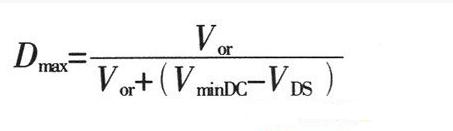
In formula: Vor is reflected voltage refracted from secondary side to primary side, when AC input is 220V, reflected voltage is 135V; VminDC - smallest constant voltage after rectification; VDS is D and S. poles when MOSFET power tube is on. The voltage between them is usually 10V.
2. The peak current IPK of primary winding of transformer is:

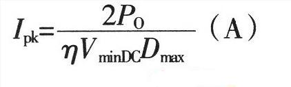
In formula: η is conversion efficiency of transformer, Po is output power rating, unit is W.
3. Transformer primary inductance LP:

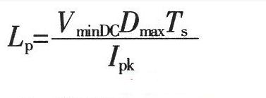
In formula: Ts is cycle(s) of switching tube, unit of LP is H.
4. Air gap lg transformer:

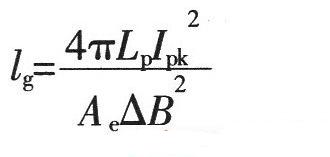
In formula: Ae is effective cross-sectional area of the magnetic circuit (cm2); △B is magnitude of change in intensity of magnetic induction of magnetic circuit (Tl); unit of Lp is H , unit of IPK is A, and unit of lg is mm.
5. Transformer Core

The power of flyback converter is usually small, and core of transformer is usually a ferrite core, and its AP power is:
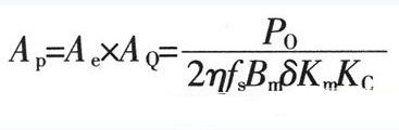
In formula: AQ is area of the core window, unit is cm2; Ae is effective cross-sectional area of the magnetic circuit, unit of measurement is cm2; Po is rated output power of transformer, unit of measurement is cm2. units W; fs - switching frequency of switch tube; Bm is maximum strength of magnetic induction of magnetic circuit, unit of measurement is T; δ is current density of coil wire, typically 200-300 A/cm2, η is conversion efficiency of transformer, Km is window fill factor, typically 0.2-0.4, KC is core fill factor, which is 1.0 for ferrite.
According to obtained AP value, choose a core with a little more margin. Generally, try to choose a core with a large window length-to-width ratio, so that window efficiency of magnetic core is higher, and leakage inductance can be reduced at same time.
6. NP transformer primary

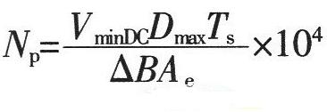
In formula: △B is value of change (T) of working strength of magnetic induction of magnetic core, unit of Ae is cm2, and unit of Ts is s.
7. NS transformer secondary turns

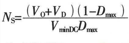
In formula: VD is forward voltage drop across rectifier diode on secondary winding of transformer.
8. Power switch tube selection

Minimum switching tube voltage UDS
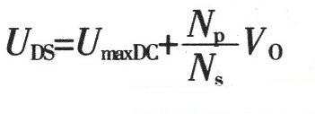
As a general rule, a MOSFET supply lamp is selected whose breakdown voltage between DS should be slightly larger than value calculated by formula (9).
9. PCU copper loss winding


The resistance value of primary and secondary windings can be obtained by calculating winding resistance value R. When calculating consumption time of copper primary winding, current is calculated from peak current IPK of primary side, copper is calculated consumption time of secondary winding, and current Use the output current Io to calculate.
10. Magnetic core loss

Magnetic core loss depends on operating frequency, operating magnetic induction, operating condition of circuit, and characteristics of selected magnetic core material. For bipolar switching transformer, core loss PC:
In formula: Pb is core loss per unit mass (W/kg) at operating frequency and operating magnetic induction; Gc is mass of core (kg).
For a unipolar switching transformer, since magnetic core operates in half of hysteresis loop region, core loss is about half that of a bipolar switching transformer. The total loss of a transformer is sum of total copper loss and the core loss.
Related
- Super practical! The 10 Most Commonly Used Power Supply Design Formulas
- Analysis and comparison of 6 most commonly used DC power supply circuits
- The most complete knowledge in history of uninterruptible power supply UPS
- 13 Commonly Used Basic Schema Formulas Beginners Should Read
- Switching Power Supply PCB Design Skills
- Countdown of 8 most commonly used diodes
- Notes on whole switching power supply design process!
- Commonly Used Peripheral Diagrams, Hardware Design Reference and Precautions
- A detailed explanation of three commonly used LED drive power schemes.
- Count 8 most commonly used diodes! How much do you know?
Hot Posts
 How to distinguish induction from leakage, we will teach you three tricks! Ordinary people can also learn super practical
- What is drowning in gold? Why Shen Jin?
- This is a metaphor for EMI/EMS/EMC that can be understood at a glance.
- How many types of pads have you seen in PCB design?
- Summary of Common PCB Repair Techniques
- What is three anti-paint? How to use it correctly?
- Knowing these rules, you will not get confused looking at circuit diagram.
- How to make anti-interference PCB design?
- Can diodes do this?