Location:Home Page > Archive Archive
Analysis and comparison of 6 most commonly used DC power supply circuits
2023-03-20【Archive】
In DC circuits, many applications require not only a DC source with zero output resistance, but also a DC source with infinite input resistance. Below are a few unipolar DC circuits:
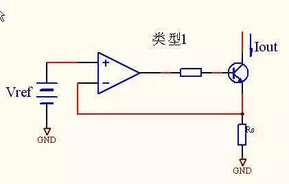
Type 1
Opportunities. High precision operational amplifier
Output current:Iout=Vref/Rs
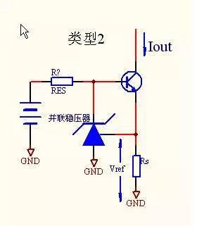
Type 2
Features:Using shunt regulator, simple and high precision output current: Iout=Vref/Rs Detection voltage:Depending on Vref (1.25V or 2.5V)

Type 3Features:Uses simple transistors, low precisionOutput current:Iout=Vbe/Rs< br >Detection voltage:about 0.6V
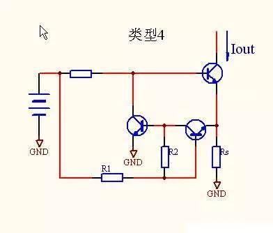
Type 4
Features: Type 3 Vbe temperature fluctuation reduction, low, medium accuracy, low voltage detection Output current:Iout=Vref/Rs Detection voltage :About 0.1V~0.6V
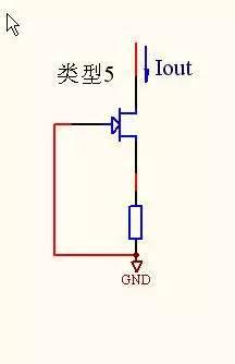
Type 5Features: Using JEFT, ultra-low noiseOutput current:Determined by JEFT < / p>
Detection voltage: refers to JEFT
Type 1 is basic circuit. During operation, input voltage Vref is equal to detection voltage Vs (Vs=Rs×Iout) proportional to output current, as shown in Figure 5.
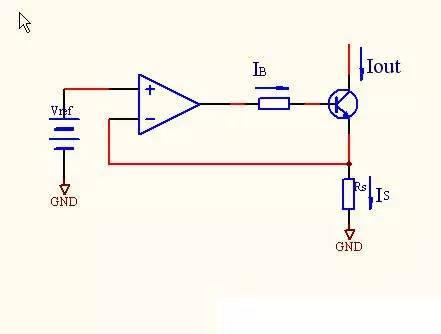
Note: Is=IB+Iout=Iout(1+1/hFE) where 1/hFE is an error. If a transistor is used in output stage, a current base error will be generated when a current is detected. this situation is not allowed, you can use as shown in Figure 6 using FET tube.

Iout=Iout-IG
Type 2, this is a shunt regulator circuit that uses an op-amp and an integrated voltage Vref (2.5V), because Vref voltage of this circuit reaches 2.5V, so power utilization range is narrow. Type 3, this is In circuit that replaces op-amp with a transistor, because Vbe (about 0.6V) of transistor is used to replace Vref circuit, temperature change of Vbe is presented at output without any change, so type 4 accuracy is less than expected, that is, a circuit is used that compensates for change in Vbe with temperature, since detection voltage is also lower than about 0.1V, power supply range is very wide. since noise is also very small, so it is useful to use this circuit when noise becomes a problem. In this circuit, if RGS is not connected, current value becomes IDSS. So J-FET is connected as a diode. Become a "DC diode"
The above circuits are current sink circuits, but other than type 2, if you change polarity of Vref and semiconductor components used, they can be made into a current sink circuit.
Related
- Analysis and comparison of 6 most commonly used DC power supply circuits
- Super practical! The 10 Most Commonly Used Power Supply Design Formulas
- List of commonly used circuits for zener diodes
- Analysis of damping RC circuit of a switching power supply "haberdashery"
- Countdown of 8 most commonly used diodes
- Detailed analysis of the "various protection schemes" of a switching power supply
- Analysis of various losses inside a switching power supply from 4 aspects
- A detailed explanation of three commonly used LED drive power schemes.
- The most complete knowledge in history of uninterruptible power supply UPS
- Anti-reverse connection is very important, make good use of these 4 commonly used circuits
Hot Posts
 How to distinguish induction from leakage, we will teach you three tricks! Ordinary people can also learn super practical
- What is drowning in gold? Why Shen Jin?
- This is a metaphor for EMI/EMS/EMC that can be understood at a glance.
- How many types of pads have you seen in PCB design?
- Summary of Common PCB Repair Techniques
- What is three anti-paint? How to use it correctly?
- Knowing these rules, you will not get confused looking at circuit diagram.
- How to make anti-interference PCB design?
- Can diodes do this?