Location:Home Page > Archive Archive
Do not underestimate "form of high-frequency magnetic core" in switching power supply, what effect does it have on transformer?
2023-03-18【Archive】
In switching power supplies, high-frequency magnetic circuits are widely used. When you encounter different shapes of high frequency magnetic circuits, can you explain difference between them?
A high-frequency transformer is a device that converts alternating voltage, current, and impedance. When there is alternating current in primary winding, an alternating magnetic flux is created in iron core (or magnetic core), which induces a voltage into secondary coil (or current). The transformer consists of an iron core (or magnetic circuit) and a coil. The roller has two or more windings. The winding connected to power supply is called primary coil, and remaining windings are called secondary coil. Transformer cores include tank cores, RM cores, E cores, EC cores, ETD and EER cores, PQ cores, EP cores, EP cores, ring cores, etc. So how do these cores affect performance of a transformer?
Please see specific analysis below.
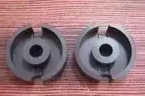
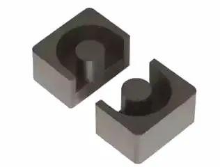
01 Pot core
The bobbin and winding are almost completely wrapped in a magnetic core, which provides a very good shielding effect against electromagnetic interference; The size of pot type magnetic core is according to IEC standard, and interchangeability is very good during operation. manufacturing; plain bobbin (no pins) and PCB spool (with pins); due to its can-shaped design, it is more expensive compared to other types of cores of same size; because its shape is not conducive to heat dissipation, it is not suitable for high power transformer inductors.
02 RM Core
Compared with pot type, two symmetrical sides of pot type are cut off, which is more conducive to heat dissipation and larger lead wires; Compared with pot type, it saves about 40% of installation space. ; There are pinless and pin bobbins; a pair of clamps can be used for installation; magnetic circuits of PM type can be made in form of flat shapes (suitable for planar current transformers or direct mounting of magnetic circuits on printed circuit boards with a developed winding scheme); although shielding effect is not as good as that of can type, it is still good.
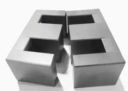
03 E Core
Compared with crucible core, cost of E-type core is much lower, and winding and assembly is relatively simple. This form of core is currently most widely used, but has disadvantage that it cannot provide self-protection. shielding; type E cores can be installed in different directions and several pairs can be stacked on top of each other to supply higher power; this type of magnetic circuit can be made in a flat form (this is a very popular form of magnetic circuit for planar transformers); it can also provide wireless communication in form of pins and coils in form of pins; Because of their excellent heat dissipation and can be used in superposition, typically high power inductors and transformers use this form of magnetic core.
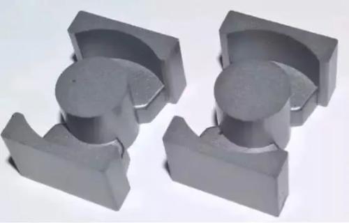
04 EC, ETD and EER cores
These types of core construction are between E-type and pot type. Like E-type cores, they can provide ample space for large gauge wires to exit (suitable for current trend of low-voltage and high-current switching power supplies); these forms of magnetic cores are also very good at heat dissipation; because center column is cylindrical, same as compared with cuboid cross section, length of single turn winding is shortened by 11%, which reduces copper loss by 11%, and at same time allows magnetic core to provide higher power output ; at same time, central column is cylindrical, and center is rectangular in comparison with column, also avoids hidden danger of damage to winding wire insulation during winding due to edge and corners of the cuboid.
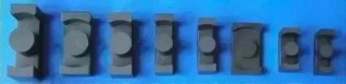
05 PQ core
PQ type magnetic circuit is specially designed for switching inductors and power supply transformers. PQ shape design optimizes ratio between core volume, surface area and winding area of the winding, this design allows you to get maximum output power with a minimum volume and weight of transformer and takes up minimal space for installing a printed circuit board; a pair of clips can be used for installation and fixation; this efficient design also makes cross-sectional area of the magnetic circuit of magnetic core more uniform, so this magnetic core structure also makes it less expensive than other magnetic core design designs, operating point.
06 EP core
The three-dimensional structure of round center column of EP core completely covers winding, except for end that is in contact with PCB board, and shielding is very good; this unique shape minimizes difference between two cores. The effect of air gap formed by contact surface during assembly provides more volume and overall space utilization.
07 Toroidal core
For manufacturer, toroidal core is most economical, and its cost is lowest among all types of comparable cores; due to use of a reel, additional costs and assembly costs are zero; when suitable Can be wound with wire winding, it is also very well shielded.

08 Overview
The above is an analysis of effect of shape of core of a high frequency transformer on operation of transformer, and I hope it can help you.
Related
- Do not underestimate "form of high-frequency magnetic core" in switching power supply, what effect does it have on transformer?
- Finally, it becomes clear that process of obtaining switching losses of a MOSFET in a switching power supply
- Notes on whole switching power supply design process!
- Engineer Daniel tells you: The "Y Capacitor" of a switching power supply is calculated in this way.
- Analysis of damping RC circuit of a switching power supply "haberdashery"
- Detailed analysis of the "various protection schemes" of a switching power supply
- Analysis of various losses inside a switching power supply from 4 aspects
- What does color of magnetic ring mean?
- Four ways to reduce the output "ripple and noise" of a switching power supply
- Switching Power Supply PCB Design Skills
Hot Posts
 How to distinguish induction from leakage, we will teach you three tricks! Ordinary people can also learn super practical
- What is drowning in gold? Why Shen Jin?
- This is a metaphor for EMI/EMS/EMC that can be understood at a glance.
- How many types of pads have you seen in PCB design?
- Summary of Common PCB Repair Techniques
- What is three anti-paint? How to use it correctly?
- Knowing these rules, you will not get confused looking at circuit diagram.
- How to make anti-interference PCB design?
- Can diodes do this?