Location:Home Page > Archive Archive
Several Effective Circuit Analysis Techniques
2023-04-10【Archive】
There are many circuit analysis methods, such as superposition theorem, branch analysis method, mesh analysis method, knot analysis method, Thévenin and Norton theorem, etc. The flexible use of these methods according to specific circuits and related conditions has of great importance for analysis of basic circuits. Now use various methods to compare specific circuits as follows.
01 Go to current method
The branch current method is a method of solving a branch current using branch current as output value and using two Kirchhoff's laws to formulate a circuit equation.
Steps of current branch analysis:
1) Assuming original current direction of each branch, mark loop bypass direction for selected loop. If there are n nodes, according to Kirchhoff's current law, there are (n-1) independent node current equations.
2) If there are m branches, formulate (m-n+1) independent circuit stress equations according to Kirchhoff's stress law. For convenience of calculation, a mesh is usually chosen as a loop (a mesh is a loop in which there are no other branches of a planar chain). For planar circuits, number of independent Kirchhoff equations for voltage is equal to number of cells.
3) Solve equations to find branch current.
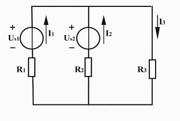
[Example 1] The circuit shown in figure above is a circuit diagram of parallel connection of generator (US1), battery (US2) and load (R3) on a vehicle. It is known that US1=12V, US2=6V, R1=R2=1Ω, R3=5Ω, find current of each branch.
Analysis: number of branches m=3, number of nodes n=2, number of grids=2. The source current direction of each branch is shown in figure, and circuit bypass is clockwise. There are three branches of circuit and there are three current unknowns to solve, so three equations are needed.
Decision. According to KCL, current column node equation (column (n-1) independent equations):
Node A: I1+I2=I3
According to KVL, column circuit voltage equation:
Grid 1: I1R1-I2R2=Us1-Us2
Grid 2: I2R2+I3R3=Us2
Solution: I1=3.8A I2=-2.2A I3=1.6A
02 Superposition theorem
In a linear circuit, response (voltage or current) generated by combined action of all independent power supplies is equal to sum of responses generated by individual power supplies.
When applying superposition theorem, you should pay attention to following points:
1) When considering one power supply, it must be assumed that other independent power supplies have a value of zero. The voltage source is changed to a short circuit, and EMF is zero, current source is open, and current is zero. However, if power supply has internal resistance, it should be left in place. The connection mode of other components remains unchanged.
2) When considering a single power supply, its reference direction should be chosen to be same as reference direction of corresponding response in original circuit, and algebraic value of response should be replaced in superposition. Or take direction of voltage and current in original circuit as a standard, take a positive sign when reference directions of divided voltage and divided current are consistent with it, and take a negative sign when they are incompatible.
3) The superposition theorem can only be used to calculate voltage and current of a linear circuit, but you cannot calculate parameters such as power and voltage or current that are not linearly related.
4) Controlled sources are not independent power sources and must be in appropriate taps.
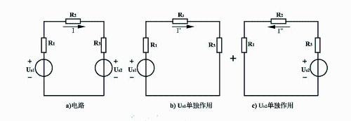
[Example 2] In following circuit, use superposition theorem to find current I3 in circuit.
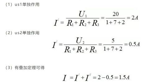
Decision. In accordance with superposition theorem, electrical circuit in figure a can be considered as a superposition of circuits in figure b and figure c
03 Mesh Analysis
Grid current is variable to be determined, and method of establishing an equation for solving circuit from CWL is called grid analysis method. The grid current equation is also called grid equation.
When applying mesh analysis method, you should pay attention to following points:
1) According to value and calculation method of grid self-resistance, mutual resistance and equivalent voltage source, final form of grid analysis equation can be written directly, which is called verification method.
2) For a circuit with a controlled voltage source, first consider controlled source as an independent power source, write grid equation according to control law, and then express controlled value of controlled source with grid current .
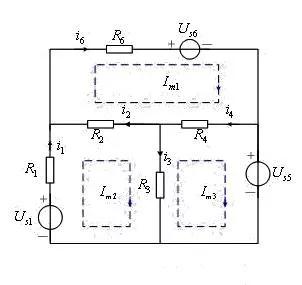
[Example 3] Write grid equation for circuit shown in figure.
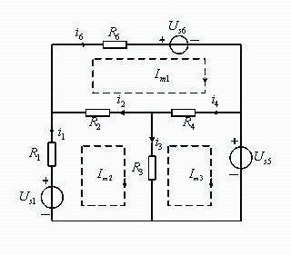
Assuming that grid current flows in grid 1, 2 and 3 respectively, grid current reference direction is shown in figure.
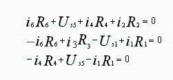
Decision. Using branch current as a variable, write KVL equation for each grid as
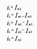
To obtain a circuit equation with grid current as unknown variable, grid current is used to represent current of each branch, i.e.:
Substitute formulas above into KVL equation to get grid current equation
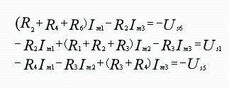
is grid equation of circuit. Obviously, grid current can be solved from these three equations.
04 Node Analysis
In a circuit with n nodes, one node is chosen as reference node, and voltage from other nodes to reference node is called node's node potential. Take node potential as variable to be determined, express current of each branch with node potential, write KCL equations for all nodes except reference node, get node potential, and then determine network analysis method of other variables. This is called point analysis.
Steps for writing a knot analysis equation:
1) Select a reference node and accept node potential of remaining n-1 independent nodes;
2) Write a KCL equation for n-1 independent nodes and current of each branch in equation is represented by node potential;
3) Solve equation to get node potential;
4) Determine other variables by node potential.
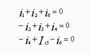
[Example 4] Write node equations for circuit shown in figure.
Solution: Let node ④ be reference node, and set voltages of independent nodes ①, ②, ③ respectively. List KCL equations of nodes ①, ② and ③ respectively as follows.
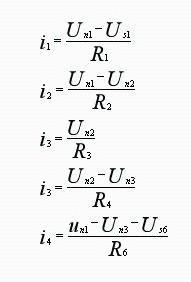
To obtain a circuit equation with node potential as unknown variable, node potential is used to represent current of each branch, i.e.:
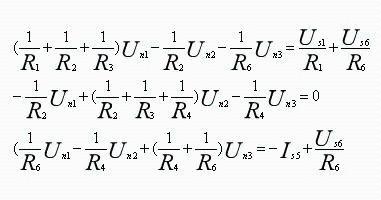
Substitute formulas above into KCL equation to get knot equation:
05 Thévenin's theorem and Norton's theorem
Thevenin's theorem and Norton's theorem are often used to obtain simplest equivalent circuit of a complex network, especially suitable for calculating voltage or current of a branch or analyzing voltage or current of a branch in which a component parameter changes. current, etc.
General steps for applying:
1) Treat circuits other than polling branches as active single-port networks;
2) When considering Thevenin equivalent circuit, calculate open-circuit voltage of an active single-port network;
3) When considering Norton equivalent circuit, calculate short circuit current isc of active single port network;
4) Calculate input impedance Req of an active single-pole network;
5) Replace original source port network with Thevenin or Norton equivalent circuit and solve circuit.
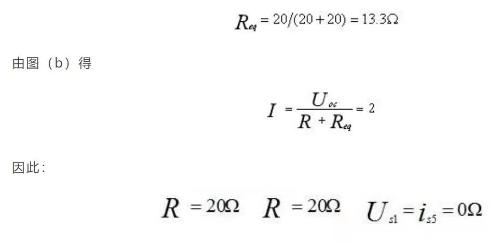
[Example 5] Current I=2A of circuit shown in figure, try to determine value of resistor R.
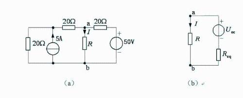
Solution: First determine equivalent of Thévenin circuit, other than resistance R, as shown in figure (b), and then determine resistance 2R with current I=2A.
Choose graph sum calculation directly. According to superposition theorem, when R is disconnected
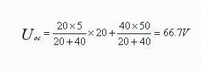
(Current source works separately Voltage source U'ab+U''ab works separately) Set independent power supply to zero, and it is easy to get equivalent resistance.
Comparison of different methods
Several of above examples illustrate judicious choice of network analysis methods. Some tasks require complex application of several methods, and examples are not given here. In short, right choice of problem solving methods can simplify problem solving process and increase efficiency of problem solving. Each network analysis method usually has its own scope. The application of Hough's law is suitable for finding current of several branches, but circuit should not be too complicated; equivalent conversion method of power supply method is suitable for circuits with a large number of power supplies; method of nodal potentials is suitable for circuits with a large number of branches and several nodes; grid The analysis method is suitable for circuits with a large number of branches, many nodes, but a small number of grids; Thévenin's theorem and superposition theorem are suitable for calculating current of a certain branch or voltage in a certain section of a circuit. The scheme of example problem above is relatively simple, and you can choose any method to solve it. For some schemes that are more complex but have certain characteristics, you should choose appropriate method to make process of solving problem simple and easy to understand. decide correctly.
1) The superposition theorem applies only to linear circuits. When applying superposition theorem to analyze circuits with controlled sources, it is usually not considered that controlled sources act on circuit by themselves, but are considered as elements of resistance. When only an independent power source is acting on circuit, controlled source remains in circuit. When overlaying, attention should be paid to whether reference direction of each response component matches direction of original response variable. If direction is consistent, a "+" sign should be placed in front of response component, and if direction is inconsistent, a "-" sign should be placed in front of response component. The superposition theorem should not be abused. It is commonly used when circuit is easy to solve when power supply acts alone, and is also often used when structure or parameters of circuit are unknown.
2) For current branch method, number of equations is equal to number of branches, and it is easy to use a computer to solve it, but if there are few unknowns, for example three, amount of calculation is too large, regardless of whether it is substituted into elimination method or determinant method. If you reduce unknowns, number of equations will decrease. Including grid current method, loop current method and nodal voltage method, it is proposed by reducing unknown quantities and reducing equations.
3) The essence of nodal analysis method The essence of nodal analysis method is to write n-1 independent KCL equations with potential of node as resulting variable, which is especially suitable for circuits with a small number of yevil. Once a reference node is selected, voltage of other nodes relative to reference node is node potential, and unknown is very easy to confirm, which is why node analysis method is often used in computer circuit analysis.
4) Thevenin and Norton theorems are often used to simplify a complex network, especially to calculate voltage or current of a certain branch, or to analyze effect of changing a parameter of a certain component on a branch. Application steps: Take a circuit other than desired branch as an active one-port network and calculate any two of three network parameters: open circuit voltage, short circuit current, and input terminal resistance.
5) In a linear circuit, response (voltage or current) generated by combined action of all independent power supplies is equal to sum of responses generated by individual power supplies.
Related
- Several Effective Circuit Analysis Techniques
- Experience in recognition of circuit diagrams of electronic circuits and method of circuit analysis
- Senior engineer summarizes 10 methods for complex circuit analysis
- List of 5 Most Practical Network Analysis Techniques! must watch
- Analysis of power circuit of a classic single-chip microcomputer
- You must learn drawing techniques and skills of 18 special circuit board routes.
- Circuit Analysis of 6 Examples Explaining Lightning Surge Protection in Detail
- Analysis of damping RC circuit of a switching power supply "haberdashery"
- Principal analysis of BUCK / BOOST circuit, a summary is also in place
- How to solve the problem with electrostatic discharge? Use several real cases to conduct a joint analysis
Hot Posts
 How to distinguish induction from leakage, we will teach you three tricks! Ordinary people can also learn super practical
- What is drowning in gold? Why Shen Jin?
- This is a metaphor for EMI/EMS/EMC that can be understood at a glance.
- How many types of pads have you seen in PCB design?
- Summary of Common PCB Repair Techniques
- What is three anti-paint? How to use it correctly?
- Knowing these rules, you will not get confused looking at circuit diagram.
- How to make anti-interference PCB design?
- Can diodes do this?