Location:Home Page > Archive Archive
Anti-reverse connection is very important, make good use of these 4 commonly used circuits
2023-05-05【Archive】
For some products that are used in everyday life, this issue will be taken into account during product development. Customers just use plug to connect power supply, so they usually use reverse plug connectors. This is a simple and inexpensive and effective method Methods.
However, for products that are at factory production stage, it may be inconvenient to use error-proof connectors, which can lead to reverse connections due to negligence of production personnel, resulting in losses. Therefore, sometimes it is necessary to add an anti-reverse switching circuit to circuit, although this increases cost. Let's talk about commonly used anti-reverse scheme.
01
The easiest way to connect a diode in series:
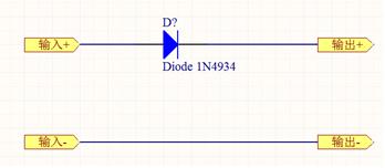
Benefits: The circuit is simple and cost is low. It is suitable for products with low current and strict cost requirements.
Disadvantages: Since PN junction of diode is turned on, a voltage drop occurs, typically below 0.7V. Such a voltage drop makes such a circuit unsuitable for use in high current circuits. If in circuit current is 10A, then power consumption of diode is 0.7 * 10 \u003d 7W, and heat dissipation is still significant. In products with compact structure and limited space, impact on product stability or human experience is still relatively large.
02
Is there a way to solve diode voltage drop problem mentioned above? See diagram below.
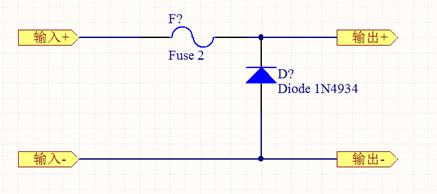
The above reverse connection circuit uses a fuse and an anti-parallel diode. The polarity of power supply is correct. When circuit is operating normally, diode is in a reverse blocking state due to presence of a load, and fuse is not blown.
When power supply is reversed, diode conducts, and current is relatively large at this time, and fuse blows, thereby cutting off power supply and protecting load.
Benefits: The voltage drop across fuse is very low and there is no heat problem. The cost is not high.
Disadvantages: When reconnected, fuse needs to be replaced and operation becomes problematic.
03
A circuit that can work fine if connected positively or vice versa:
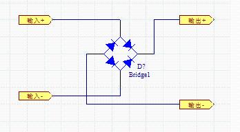
Benefits: No matter how input connector is connected, circuit can work normally.
Cons: there is a voltage drop across two diodes. Suitable for low current circuits.
04
Determined by manufacturing process of field tube, on-resistance of field tube is relatively low. It is a very commonly used switching device, especially in high power applications. On example of IRFR1205 in TO-252 package, its main parameters are as follows: Vdss=55V, Id=44A, Rds=0.027 Ohm, it can be seen that its open resistance is only 27 mOhm.
The figure below shows an anti-reverse connection circuit consisting of N-channel FETs.
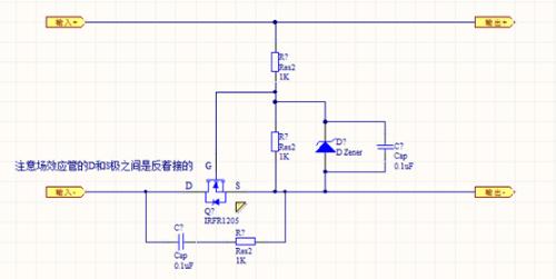
The biggest feature of this circuit is way D pole and S pole of field tube are connected. Generally, when we use an N-channel amplifying MOS tube, current usually enters from D pole and leaves S pole. The opposite is true for this circuit.
I saw this diagram on a forum and organizer who released this diagram was criticized by many netizens. It cannot be said that there is a diode between DP. The landlord did not specify name of field tube pin. Due to inertial approach to application of field tube, landlord was wrong. In fact, as long as there is an appropriate voltage between G and S poles, FET will be fully turned on. After switching on, it is, as it were, closed by a switch between D and S, and current has same resistance from D to S or from S to D.
With correct polarity of power supply, current begins to flow through voltage regulator of FET, and voltage of S pole is close to 0 V. After two resistors share voltage, voltage G is applied to turn on FET. Since its conduction resistance is very small, diode inside FET is replaced.
When power supply is reversed, diode in FET will not conduct current until breakdown voltage is reached. No current flows through voltage divider resistor, which cannot supply G pole voltage and is not conductive. Thus, they play a protective role.
For a zener diode connected in parallel with voltage divider resistor in circuit, because input resistance of FET is very high, it is a voltage controlled device and voltage of G pole must be controlled. within 20 V. This will lead to a breakdown of G pole, and this zener diode should protect FET from breakdown.
For a capacitor connected in parallel with voltage divider resistor, a soft start effect occurs. At moment when current begins to flow, capacitor is charged, and voltage of electrode G is gradually established.
For a series circuit of resistance and capacitance in parallel between FETs D and S, I think this is still debatable. Series resistance-capacitance circuits are commonly used to absorb or delay a pulse. The use here depends on load situation and adding it may not be practical. After all, this will lead to a short turn-on pulse when power is reversed.
P-channel FETs can also be used, but device must be connected in series to positive input terminal. Not described here.
Related
- Anti-reverse connection is very important, make good use of these 4 commonly used circuits
- List of commonly used circuits for zener diodes
- The triode is used as a switch. You should know function of these capacitors which are commonly used.
- Analysis and comparison of 6 most commonly used DC power supply circuits
- Commonly used models of rectifier diodes, what are important parameters?
- Commonly Used Diode Circuits Essential for Engineers
- How many of these free and easy to use circuit design programs have you used?
- Countdown of 8 most commonly used diodes
- What is three anti-paint? How to use it correctly?
- A list of some of the tools commonly used by electronic engineers.
Hot Posts
 How to distinguish induction from leakage, we will teach you three tricks! Ordinary people can also learn super practical
- What is drowning in gold? Why Shen Jin?
- This is a metaphor for EMI/EMS/EMC that can be understood at a glance.
- How many types of pads have you seen in PCB design?
- Summary of Common PCB Repair Techniques
- What is three anti-paint? How to use it correctly?
- Knowing these rules, you will not get confused looking at circuit diagram.
- How to make anti-interference PCB design?
- Can diodes do this?