Location:Home Page > Archive Archive
Principle of electronic switch to realize overcurrent protection
2023-03-18【Archive】
An electronic switch or smart switch (Smart Switch) is a smart device based on integrated circuit technology. It features small size, low power consumption, fast response and low impedance, and can provide high reliability. Overcurrent protection is an ideal replacement for self-resetting fuses.
Take AAT4610 as an example, its overcurrent protection can be completed within 1μs, and its response speed is 1 million times faster than that of PolySwitch, and its current limiting effect on instantaneous peak current and surge current is very obvious. Therefore, electronic switches have developed extremely rapidly since their introduction, and many companies have released related products such as AAT's AAT4610, Maxim's MAX1946, NEC's µPD16875, Microsemi's SL03-SL24 series and SM03-36 series, and USB02 and USB302. etc., they can be used to protect I/O ports from overcurrent.
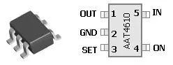
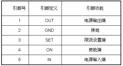
Fig. 1. Definition of AAT4610 pins
We still take AAT4610 as an example to illustrate working principle of an electronic switch to realize overcurrent protection. The AAT4610 uses a SOT-23 plastic package (as shown in Figure 1), and five pin definitions are shown in Table 1.
AAT4610 combines a 6V/2A P-channel MOSFET, gate driver, voltage reference, current-limiting comparator, and undervoltage blocking circuitry in a SOT-23-5 package (as shown in Figure 2) . . The MOSFET is an electronic switch whose on/off is controlled by output voltage of comparator. If output current is greater than set current, AMP op amp outputs a negative voltage, turns off MOSFET, stops output voltage, and protects power circuit. The MOSFET channel resistance is 180 mΩ maximum, and quiescent current in shutdown mode is 1 mA. The operating voltage of MOSFET is 2.7V ~ 5.5V. When input voltage is lower than 2.7V, undervoltage blocking circuit turns off MOSFET to protect power circuit from undervoltage.
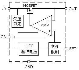
Fig. 2. AAT4610 Internal Logic Block Diagram
The application diagram of AAT4610 is very simple, if two filter capacitors and RSET resistor are externally connected, overcurrent protection function can be realized, as shown in figure 3.
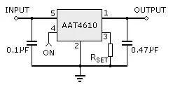
A filter capacitor is connected to input and output of AAT4610 to eliminate operating noise of electronic switch, and a current-limiting resistor RSET is used to set protection current value. When running current exceeds protection current value, output voltage immediately drops to 0 volts, and response time is about 800 ns. Pin 4 is a turn-on terminal, and it can work when input voltage is higher than 2.5V from outside, otherwise AAT4610 will have no protective effect.
Related
- Principle of electronic switch to realize overcurrent protection
- Experience in recognition of circuit diagrams of electronic circuits and method of circuit analysis
- A list of some of the tools commonly used by electronic engineers.
- Haberdashery|General failure mechanism and analysis of electronic components
- Leaving aside calculations, in principle workflow of LLC
- Detailed analysis of the "various protection schemes" of a switching power supply
- Please remember these 4 points to switch power supply in order to "comply with safety regulations".
- Circuit Analysis of 6 Examples Explaining Lightning Surge Protection in Detail
- The triode is used as a switch. You should know function of these capacitors which are commonly used.
- Schottky diode principle
Hot Posts
 How to distinguish induction from leakage, we will teach you three tricks! Ordinary people can also learn super practical
- What is drowning in gold? Why Shen Jin?
- This is a metaphor for EMI/EMS/EMC that can be understood at a glance.
- How many types of pads have you seen in PCB design?
- Summary of Common PCB Repair Techniques
- What is three anti-paint? How to use it correctly?
- Knowing these rules, you will not get confused looking at circuit diagram.
- How to make anti-interference PCB design?
- Can diodes do this?