Location:Home Page > Archive Archive
Practical capacitive buck circuit
2023-11-23【Archive】
A practical capacitive buck circuit
A common way to convert AC power to low voltage DC power is to use a transformer to step down voltage and then rectify and filter. When limited by factors such as size and cost, simplest and most practical method is to use a capacitor. step down power supply.
When using capacitors to reduce voltage, pay attention to following points:
1 Select appropriate capacitor according to load current and AC operating frequency, not load voltage and power.
2 The current-limiting capacitors should use non-polar capacitors, and electrolytic capacitors should not be used, and withstand voltage of capacitors should be higher than 400V. The ideal capacitor is an oil-filled capacitor in an iron case.
3 The step-down capacitor cannot be used in high power environments as it is unsafe.
4 Capacitive buck converters are not suitable for dynamic loading conditions.
5 Similarly, capacitor buck converters are not suitable for capacitive and inductive loads.
6 When DC operation is required, half-wave rectification should be used as much as possible, bridge rectification is not recommended, and constant load condition should be met.
This type of circuit is typically used to provide non-isolated low current power supplies at a low cost. Its output voltage can typically range from a few volts to tens of volts, depending on zener diode used. The amount of current that can be provided is proportional to capacitance of current limiting capacitor. When using half-wave rectification, current (average value) that can be obtained per microfarad capacitance is: (SI unit)
I(AV)=0.44×V/Zc=0.44×220×2×Pi×f×C =0.44×220×2×3.14×50×C=30000C =30000× 0.000001=0.03A=30mA
If full-wave rectification is used, twice current (average value) can be obtained as:
I(AV)=0.89×V/Zc=0.89×220×2×Pi×f×C =0.89×220×2×3.14×50×C=60000C =60000× 0.000001=0.06A=60mA
In general, although current of this type of full-wave rectification is slightly larger, because of floating ground, stability and safety is worse than that of half-wave rectifier type, so it is used less.
When using this scheme, you need to pay attention to following:
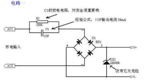
1. It is not isolated from 220V AC high voltage, pay attention to safety and avoid electric shock!
2. A current-limiting capacitor must be connected to current-carrying wire, withstand voltage must be large enough (more than 400V), and a series of anti-shock and safety resistors, as well as parallel discharge resistors, must be added.
3. Pay attention to power consumption of Zener tube, and it is strictly forbidden to disconnect Zener tube.
The simplest capacitive buck DC power supply circuit and its equivalent are shown in figure, C1 is a buck capacitor, typically 0.33-3.3uF. Suppose C1=2uF, its capacitance XCL=1/(2PI×fC1)=1592. Since on-state rectifier tube resistance is only a few ohms, dynamic resistance of VS regulator tube is about 10 ohms, current-limiting resistor R1 and load resistor RL are generally 100-200 ohms, and filter capacitor is usually 100uF ~ 1000uF, and its capacitance very small and can be neglected.
If R is used to represent equivalent resistance of all components except C1, you can draw equivalent AC circuit in figure. At same time, condition XC1>R is satisfied, so voltage vector can be drawn. Since R is much smaller than XC1, voltage drop VR across R is also much smaller than voltage drop across C1, so VC1 is approximately equal to supply voltage V, that is, VC1 =V. According to electrotechnical principle, ratio between average value of Id of rectified direct current and average value of I of alternating current is Id=V/XC1. If C1 is in uF, then Id is in milliamps. For AC 220 V, 50 Hz, you can get Id = 0.62C1.
The following two conclusions can be drawn from this: (1) When using a power transformer as a power supply for rectifier, after determining parameters in circuit, output voltage remains constant, and output current Id changes depending on increase or decrease in load (2) When using step-down capacitor as a rectifier circuit, since Id=0.62 C1, it can be seen that Id is proportional to C1, that is, after determining C1, output current Id is constant, and output constant voltage varies depending on load resistance R, value changes in a certain range.
The smaller RL, lower output voltage, and larger RL, higher output voltage. The value of C1 must be selected according to load current. For example, load circuit requires an operating voltage of 9V and average load current is 75mA. Since Id = 0.62C1, it can be calculated that C1 = 1.2uF. Taking into account losses on regulator lamp VD5, C1 can be 1.5 uF, and actual current provided by power supply, Id = 93 mA.
The value of regulated voltage of zener diode must be equal to operating voltage of load circuit, and selection of its stable current is also very important. Since capacitive buck power supply provides constant current, which is roughly a constant current source, it is generally not afraid of short circuiting load, but when load is fully opened, entire current of 93 mA will pass through loops R1 and VD5, so maximum stability of VD5 The current should be 100mA . Since RL is connected in parallel with VD5, while ensuring that RL takes 75 mA of operating current, VD5 still has 18 mA of current flowing through it, so its mThe minimum stable current should not be more than 18mA, otherwise it will lose its voltage stabilizing effect.
The value of current-limiting resistor should not be too large, otherwise it will increase power loss and also increase C2 withstand voltage requirement. If R1 = 100 ohms and voltage drop across R1 is 9.3V, loss is 0.86W and a 100 ohm and 1W resistance can be used.
The filter capacitor usually takes from 100uF to 1000uF, but pay attention to selection of its resistance. As mentioned above, load voltage is 9V, voltage drop across R1 is 9.3V, and total voltage drop is 18.3V. Q. Given that there is a certain margin, it is better that withstand voltage of C2 be higher than 25V.
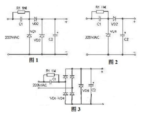
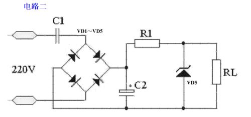
As shown in Figure 1, C1 is a step-down capacitor, D2 is a half-wave rectifier diode, D1 provides a discharge circuit for C1 in negative half-cycle of network, D3 is a zener diode R1 , charge-discharge diode C1 after resistance power is turned off. The scheme shown in fig. 2 is often used in practical applications. When it is necessary to provide more current to load, bridge rectifier circuit shown in Figure 3 can be used. The unregulated DC voltage after rectification is typically over 30V and will fluctuate greatly as load current changes. This is due to large internal resistance of this type of power supply, so it is not suitable for a high current power supply. application cases.
Device Selection
1. When designing a circuit, first determine exact value of load current, and then refer to example to select capacity of step-down capacitor. Because current Io supplied to load through step-down capacitor C1 is actually charging and discharging current Ic flowing through C1 . The larger capacitance C1 and smaller capacitive reactance Xc , greater charging and discharging current flowing through C1 . When load current Io is less than charge and discharge current C1 , excess current will flow through Zener tube. If maximum allowable current Idmax of Zener tube is less than Ic-Io , it is easy to burn out.
2. To ensure safe operation of C1 , its withstand voltage must be more than twice power supply voltage. 3. The choice of discharge resistor R1 should ensure that charge on C1 is discharged within required time.
Design example
In Figure 2 , C1 is known to be 0.33µF and AC input voltage is 220V/50Hz. Find maximum current that circuit can supply to load.
Capacitance Xc C1 in circuit:
Xc=1 /(2 πf C)= 1/(2*3.14*50*0.33*10-6)= 9.65K The charging current (Ic) flowing through capacitor C1 is equal to: Ic = U / Xc = 220 / 9.65 = 22 mA.
Typically, relationship between capacitance C of a step-down capacitor C1 and load current Io can be approximated as: C=14.5 I, where unit of capacitance C is µF and unit of Io is A.
The capacitive buck power supply is a non-isolated power supply. Particular attention should be paid to insulation to avoid electric shock.
The unregulated DC voltage after rectification is typically above 30V and will fluctuate greatly as load current changes. This is due to large internal resistance of this type of power supply, so it is not suitable for applications. high current power supply. A capacitor buck power supply is a type of non-isolated power supply. Particular attention should be paid to insulation when applied to prevent electrical shock.critical current. The operation principle of a capacitor buck power supply is not complicated to limit maximum operating current. For example, at a mains frequency of 50 Hz, capacitance generated by a 1 uF capacitor is about 3180 ohms. When 220V AC is applied to both ends of capacitor, maximum current flowing through capacitor is about 70mA.
Although current flowing through capacitor is 70mA, it does not draw any power across capacitor. It must be case that if capacitor is an ideal capacitor, current flowing through capacitor is imaginary part current and work is reactive power. According to this feature, if we connect a resistive element in series with a 1uF capacitor, voltage obtained across resistive element and power consumed by it are completely dependent on characteristics of resistive element.
For example, we connect a 110V/8W light bulb in series with a 1uF capacitor. When it is connected to 220V/50Hz AC voltage, bulb lights up and emits normal brightness without burning out, because 110V/8W current drawn by bulb is 8W/110V=72mA, which is consistent with current-limiting specifications created by a 1 uF capacitor. 50Hz AC, light bulb will also stay on without burning out. Since operating current of a 5W/65V lamp is also about 70mA, so capacitive step-down actually uses capacitive reactance to limit current, and capacitor actually plays role of current limiting and dynamically distributes voltage across capacitor and load.
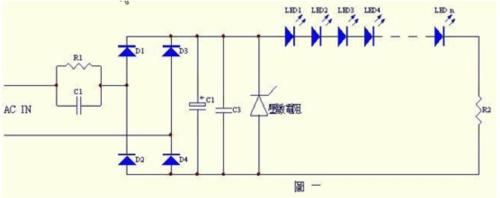
In fig. 1 shows an actual LED driving circuit using a step-down capacitor. Note that most application circuits do not use varistors or transistors to suppress transient voltages. discharge sudden change current at moment of sudden voltage change (such as lightning, start of large electrical equipment, etc.) to protect secondary gate and other transistors, and their response time is usually at micromillisecond level.
How circuit works
The role of capacitor C1 is to step down and limit current: Everyone knows that characteristics of capacitors block AC and DC current. When a capacitor is connected to an AC circuit, formula for calculating its capacitance is:
XC = 1/2πf C
In formula, XC is capacitive reactance of capacitor, f is frequency of input AC power supply, and C is capacitance of step-down capacitor.
The formula for calculating current flowing through capacitor step-down circuit is:
I = U/XC
In formula, I represents current flowing through capacitor, U represents power supply voltage, and XC represents capacitive reactance of capacitor
In a 220V﹑50Hz AC circuit, when load voltage is much lower than 220V, relationship between current and capacity will be as follows:
I = 69C, where capacitance is µF and current is mA
The table below shows a comparison between theoretical current and actual measured current in a 220V﹑50Hz AC circuit
Resistor R1 is a discharge resistor. Its function is: when sine wave breaks at time of maximum peak, residual charge on capacitor C1 cannot be released and will exist for a long time. If human body touches metal part of C1 during maintenance. There is a high probability of electric shock, and presence of resistor R1 can discharge residual charge, thereby ensuring safety of man and machine. The value of reset resistor is related to size of capacitor. Generally, larger capacitance, more residual charge and smaller value of reset resistor. Empirical data is provided below for design reference:
The function of D1 ~ D4 is rectification, and their function is to rectify AC into a ripple DC voltage.
The role of capacitors C2 and C3 is to filter, and their function is to convert rectified pulsating DC voltage into a stable DC voltage
The function of a varistor (or transient suppression transistor) is to discharge an instantaneous pulsed high voltage in input power supply to ground to protect LED from being destroyed by an instantaneous high voltage.spinning.
The number of LEDs connected in series depends on their forward voltage (Vf). In AC 220V circuit, maximum number can reach about 80. Component selection: It is generally required that withstand voltage of capacitor be greater than peak value of input supply voltage. In AC 220V, 50Hz circuit, you can choose a polyester capacitor or a capacitor from paper dielectric with a withstand voltage of more than 400 volts.
D1 ~ D4 can choose IN4007.
The withstand voltage of filter capacitors C2 and C3 depends on load voltage, which is typically 1.2 times load voltage. Its capacitance depends on magnitude of load current.
Related
- Practical capacitive buck circuit
- Buck circuit inductance calculation 2
- USB multi-output power supply --- circuit diagram 2 (BUCK discrete circuit)
- Principal analysis of BUCK / BOOST circuit, a summary is also in place
- Three circuit diagrams to teach you how to understand how a buck RC works
- Practical Skills: Explain steps of circuit board puzzle in detail.
- 40 Practical Analog Circuit Tips That 90% of People Will Ignore
- Is printed circuit board covered with copper very “up to mark”? One article to help you get practical guidelines and norms
- Buck Output Capacity Calculation
- Sharing 9 circuit designs switching power supply, circuit diagram, circuit board, application notes
Hot Posts
 How to distinguish induction from leakage, we will teach you three tricks! Ordinary people can also learn super practical
- What is drowning in gold? Why Shen Jin?
- This is a metaphor for EMI/EMS/EMC that can be understood at a glance.
- How many types of pads have you seen in PCB design?
- Summary of Common PCB Repair Techniques
- What is three anti-paint? How to use it correctly?
- Knowing these rules, you will not get confused looking at circuit diagram.
- How to make anti-interference PCB design?
- Can diodes do this?